Apparatus and method for rotating sleeve engine hydrodynamic seal

Active Publication Date: 2006-02-28
DARDALIS DIMITRIOS
View PDF8 Cites 17 Cited by
  • Summary
  • Abstract
  • Description
  • Claims
  • Application Information

AI Technical Summary

Benefits of technology

[0016]An objective of the rotation of the liner, or sleeve, in the RLE is to maintain a sliding motion between the piston rings and liner close to top and bottom dead center in order to provide a hydrodynamic lubrication regime throughout the piston stroke. In one embodiment of the RLE, a flange on the upper part of the liner transfers the thrust loads to the cylinder head and the block. The flange also reinforces the upper part of the sleeve, thereby preventing or minimizing the sleeve expansion due to high cylinder pressure that occurs when the piston is in proximity to top dead center.
[0017]One technical challenge of the RLE is to provide a seal between the rotating cylinder liner and the stationary cylinder head. This seal preferably has low friction, long life, significantly lower gas leakage than through the ring-pack, and low lubricant leakage into the combustion chamber. During each combustion cycle, the gas pressure typically cycles quickly between a relatively low pressure and a relatively high pressure at the top of the piston stroke. It is desirable that the seal work effectively throughout this range of gas pressures, and that the seal not significantly increase the amount of oil introduced into the combustion chamber.
[0018]One embodiment of the current invention provides a hydrodynamic face seal between the liner or the liner flange and the cylinder head. A hydrodynamic face seal is a seal where the rubbing surfaces slide with no metal-to-metal contact via a lubricant layer such as oil. In a hydrodynamic face seal, the gap between the surfaces is small enough to seal, thereby minimizing gas leakage. The advantage of a hydrodynamic face seal is that a small quantity of lubricant can exist in the sealing gap, and since the viscosity of the lubricant is very much higher than the gas, it will essentially block gas leakage. It is generally accepted that most of the gas leakage in engine piston rings is through the end-gap, and the only time when some gas leakage occurs in the main ring / liner sealing gap is when bore distortions increase the film thickness locally. Therefore, if a hydrodynamic face seal can be provided with no end-gap, and if a lubricant can be maintained in the sealing gap, then gas leakage can be virtually blocked.

Problems solved by technology

One technical challenge of the RLE is to provide a seal between the rotating cylinder liner and the stationary cylinder head.

Method used


Image

  • Apparatus and method for rotating sleeve engine hydrodynamic seal
  • Apparatus and method for rotating sleeve engine hydrodynamic seal
  • Apparatus and method for rotating sleeve engine hydrodynamic seal

Examples


Embodiment Construction

Hydrodynamic Face Seal

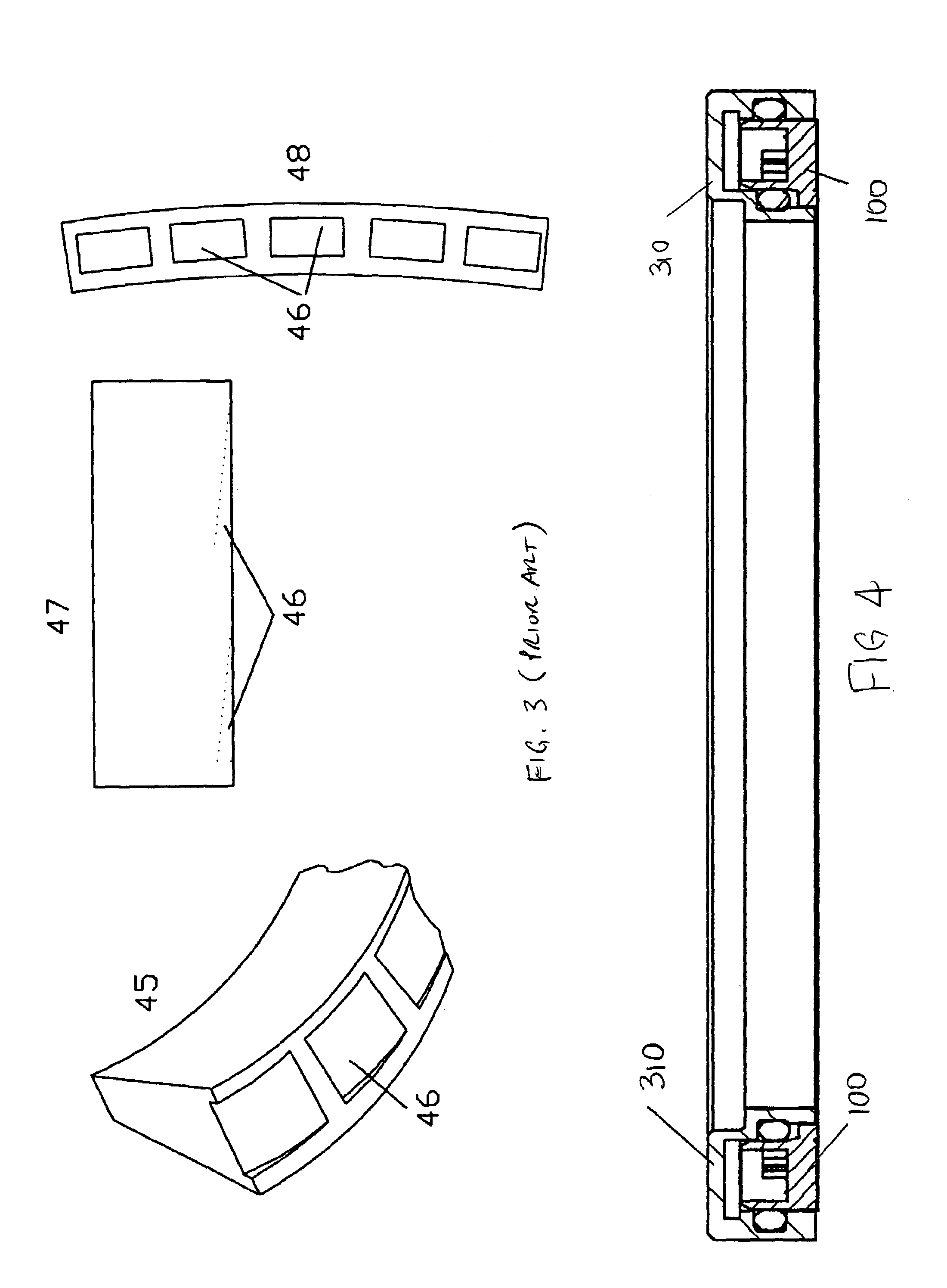
[0038]FIG. 4 is a side view of a hydrodynamic face seal 100 which is positioned within a head insert 310. Each cylinder in an RLE will typically have a rotating sleeve or liner, and a seal between the rotating liner and the cylinder head.

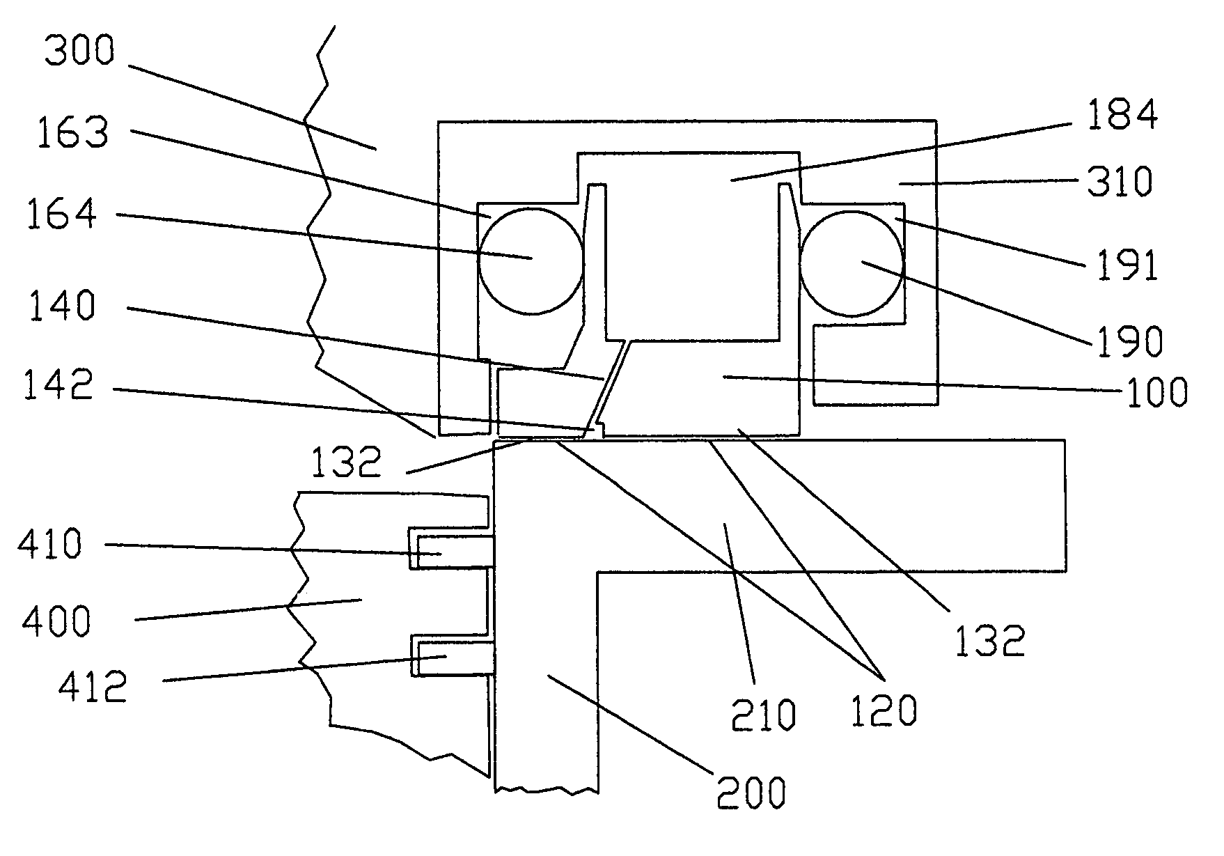
[0039]FIG. 5A shows the relative position of an example hydrodynamic face seal 100 sealing the interface of the rotating liner 200 and the cylinder head 300. A portion of a piston 400 and piston rings 410, 412 are shown for reference. In this example, the rotating liner includes a top flange 210. The bottom surface, or face, 120 of the face seal 100 provides a sealing zone 130 and a loading zone 132 between the seal 100 and the top flange 210. The face seal is typically positioned in a head insert 310 in the cylinder head 300. An oil supply cavity 184 is located in head insert above the face seal 100, and oil is provided from this oil supply cavity to the sealing zone and loading zone. Oil is provided from this oil supply cavit...


PUM


Abstract

A hydrodynamic face seal 100 for sealing between the cylinder head 300 and rotating sleeve 200 of a rotating liner engine. The face of the face seal provides a sealing zone 130 for maintaining a lubricant layer of about 2 micrometers between the face seal and the sleeve; and a loading zone 132. The loading zone includes hydrodynamic lift features such as inclined pads 150 or recessed step pads 152. Oil is supplied to annular oil supply passage 142 between the sealing zone and the loading zone, and flows from the annular oil supply passage to radial passages 144 located between the step pads. A spring pre-load is provided to the seal. An outer secondary seal 190 is provided to contain the lubricant. One or more inner secondary seals is provided to contain lubricant and combustion gases. Spiral oil pumping grooves may be provided.

Description

RELATED APPLICATIONS[0001]This application is related to and claims priority from applicants' U.S. Provisional Patent Application No. 60 / 461,496 filed Apr. 9, 2003.BACKGROUND[0002]1. Field of Invention[0003]This invention relates to a method and apparatus for a hydrodynamic face seal between a rotating cylinder liner and a cylinder head in an internal combustion engine.[0004]2. Description of Prior Art[0005]This patent describes improved sealing methods and mechanisms between the cylinder liner and the cylinder head of a rotating sleeve engine or rotating liner engine (RLE). In a conventional engine, a seal between the cylinder head and stationary cylinder is typically obtained by compressing a head gasket between the head and the cylinder. Since the RLE has a rotating liner, an alternate means of sealing between the block and the liner is required.Prior Art—The '872 Patent[0006]The RLE is described in U.S. Pat. No. 6,289,872 issued Sep. 18, 2001 to applicant Dardalis. The '872 pate...

Claims


Application Information

Patent Timeline
Patent Type & Authority Patents(United States)
IPC IPC(8): F01L7/02F01B15/00F01B15/06F01L7/04F01L7/16F01M9/10F02F11/00F16J10/00F16J15/34
CPCF01B15/007F01B15/06F01L7/04F01L7/16F16J15/342F01M9/109F02F11/007F16J10/00F01L2101/00F01L2301/00
Inventor DARDALIS, DIMITRIOS
Owner DARDALIS DIMITRIOS
Why Eureka
Try Eureka