Auxiliary-driving system in engine

Inactive Publication Date: 2006-02-28
HONDA MOTOR CO LTD
View PDF13 Cites 11 Cited by
  • Summary
  • Abstract
  • Description
  • Claims
  • Application Information

AI Technical Summary

Benefits of technology

[0007]It is therefore an object of the present invention to provide a new auxiliary-driving system in an engine, wherein an idler pulley having a tensioner function is located on an uppermost portion of a transmitting belt, thereby facilitating the adjustment of the tension of the transmitting belt and other maintenance; and both reeving angle of an inner surface of the belt with respect to an auxiliary pulley and reeving angle of an outer surface of the belt with respect to an auxiliary pulley can be ensured as large as possible, thereby enhancing the transmitting efficiency of the transmitting belt; and compactness of the auxiliary-driving system itself and reduction in cost thereof can be achieved.
[0008]To achieve the above object, according to a first feature of the present invention, there is provided an auxiliary-driving system in an engine, adapted to drive auxiliaries supported on an engine body by a crankshaft of the engine body, comprising: a crank pulley, a first auxiliary pulley and an idler pulley having a tensioner function, which are disposed in a triangular configuration with the idler pulley located in an uppermost position, on one side of the engine body in a direction perpendicular to the crankshaft; a second auxiliary pulley disposed in a space surrounded by these pulleys, and an endless transmitting belt reeved around the crank pulley, the idler pulley, the first auxiliary pulley and the second auxiliary pulley; an inner surface of the transmitting belt being reeved around the first auxiliary pulley, and an outer surface of the transmitting belt being reeved around the second auxiliary pulley. With this arra

Problems solved by technology

However, the conventionally known system suffers from a problem that the tensioner is disposed at a vertically intermediate portion of the endless transmitting belt, and further, at a location closer to the engine body.
Hence, it is difficult to conduct the adjustment of the tensioner and to perform other necessary maintenance.
The conventionally know

Method used


Image

  • Auxiliary-driving system in engine
  • Auxiliary-driving system in engine
  • Auxiliary-driving system in engine

Examples


Embodiment Construction

[0014]The mode for carrying out the present invention will now be described by way of an embodiment of the present invention shown in the accompanying drawings.

[0015]The present embodiment shows a case where an auxiliary-driving system of the present invention is utilized in an engine for an automobile.

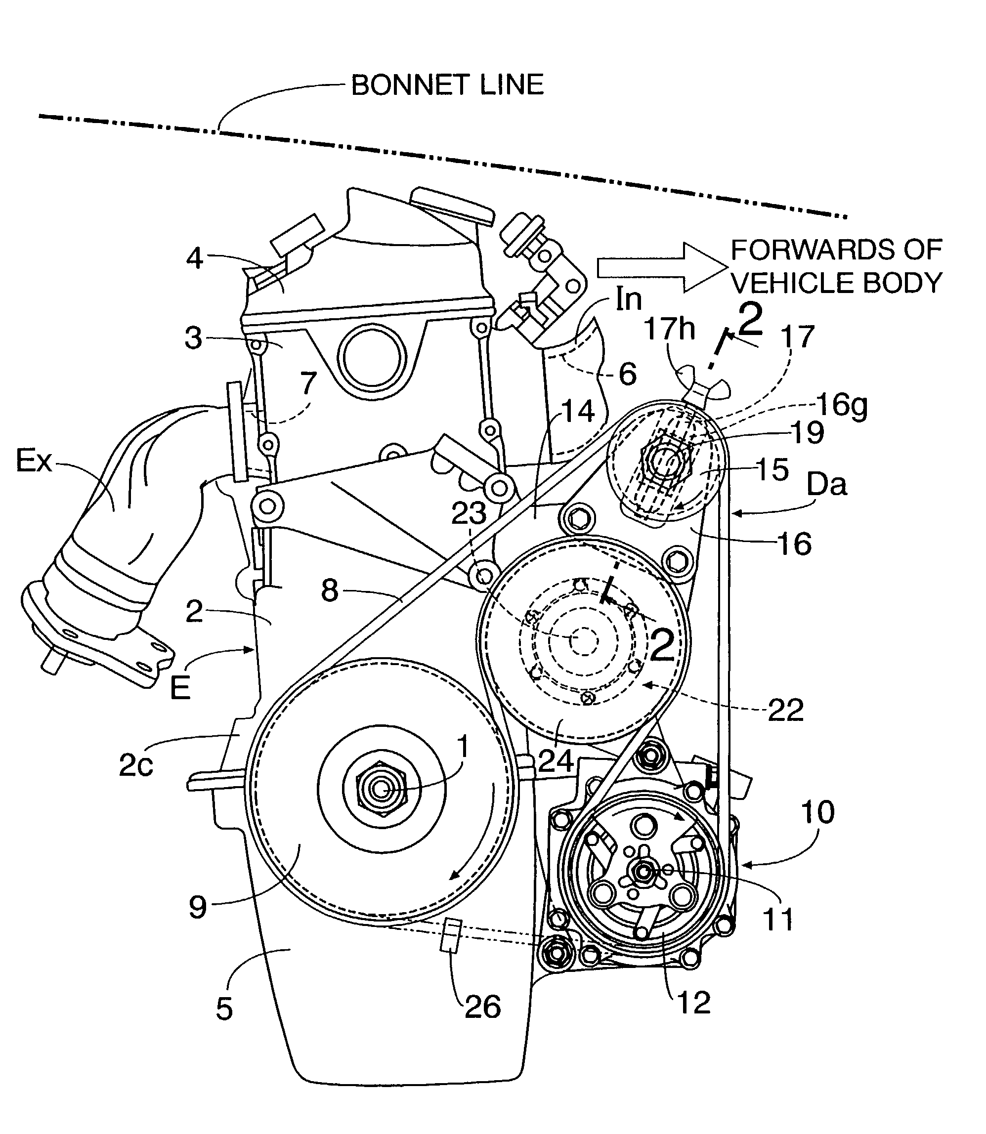
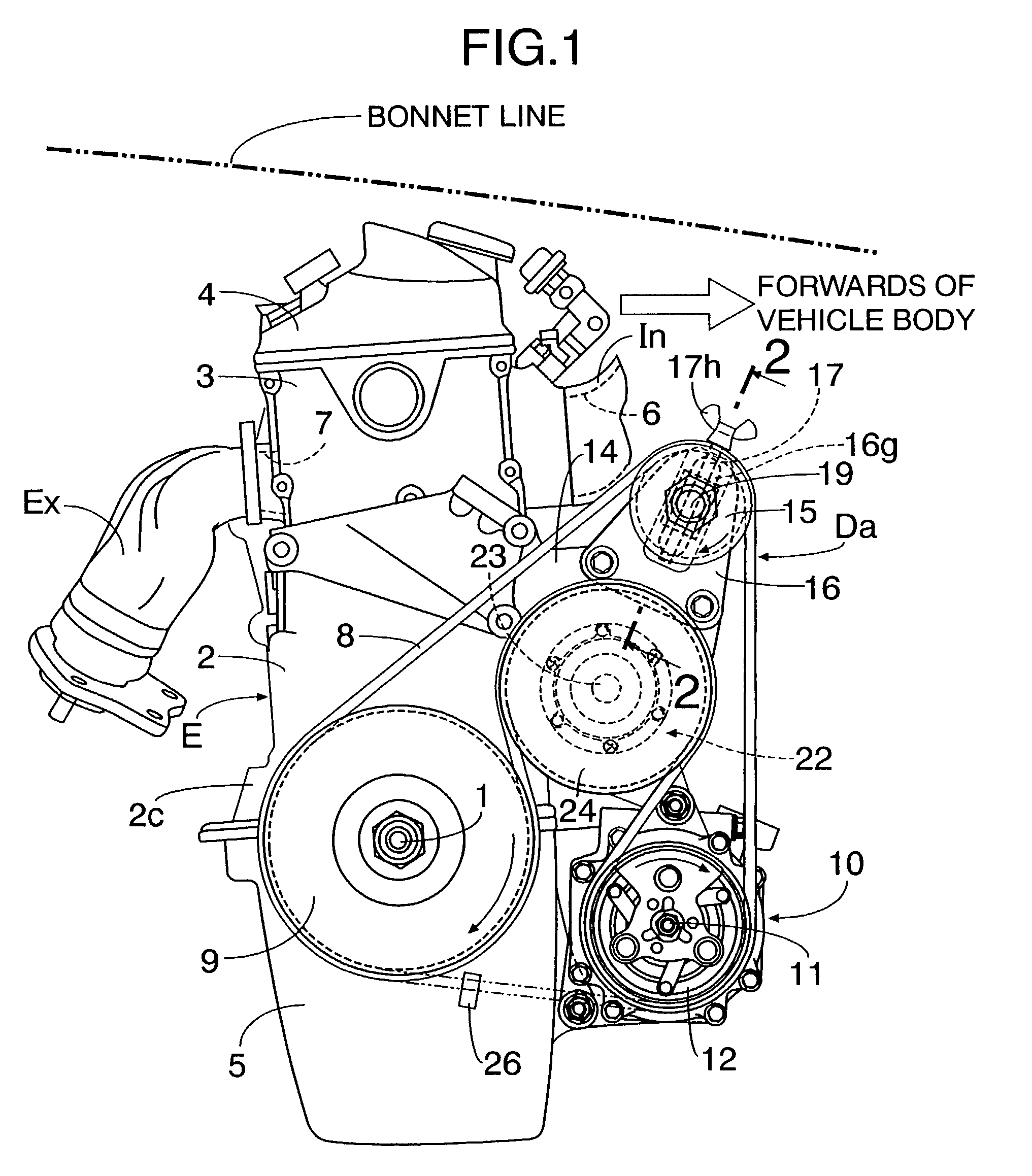
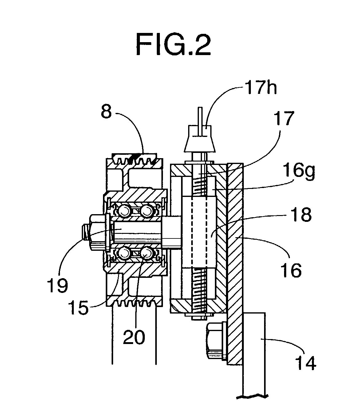
[0016]Referring to FIG. 1, an engine body E of an in-line multi-cylinder 4-cycle engine is disposed laterally at a front portion of a vehicle body of an automobile, i.e., a crankshaft 1 thereof is disposed in a direction perpendicular to a longitudinal direction of the vehicle body. The engine body E includes a cylinder block 2 in which a plurality of cylinders are arranged in line, a cylinder head 3 coupled onto the cylinder block 2, a head cover 4 covering an upper surface of the cylinder head 3, and an oil pan 5 coupled to a lower surface of a crankcase portion 2c of the cylinder block 2. A crankshaft 1 is rotatably carried in the crankcase portion 2c. An intake port 6 connected to...


PUM


Abstract

In an auxiliary-driving system in an engine, a crank pulley, a first auxiliary pulley and an idler pulley having a tensioner function are disposed in a triangular configuration with the idler pulley located in an uppermost position; and a second auxiliary pulley is disposed in a space surrounded by these pulleys. An endless transmitting belt is reeved around the pulleys. An inner surface of the transmitting belt is reeved around the first auxiliary pulley; and an outer surface of the transmitting belt is reeved around the second auxiliary pulley. Thus, the adjustment of the tension of the transmitting belt and other maintenance are facilitated, the transmitting efficiency of the transmitting belt can be enhanced, and compactness of the auxiliary-driving system itself and improvement in mileage can be achieved.

Description

BACKGROUND OF THE INVENTION[0001]1. Field of the Invention[0002]The present invention generally relates to an auxiliary-driving system in an engine, which is adapted to drive auxiliaries supported on an engine body by a crankshaft of the engine body through a driving mechanism comprising pulleys and a transmitting belt.[0003]2. Discussion of the Related Art[0004]There is a conventionally known auxiliary-driving system in an engine for driving an automobile or the like, in which an endless belt is reeved, on one side of an engine body in a direction perpendicular to a crankshaft, around a crank pulley fixed to a crankshaft, a plurality of auxiliary pulleys for driving auxiliaries supported on the engine body and a tensioner, as shown in FIG. 3A and in FIG. 3B.[0005]However, the conventionally known system suffers from a problem that the tensioner is disposed at a vertically intermediate portion of the endless transmitting belt, and further, at a location closer to the engine body. He...

Claims


Application Information

Patent Timeline
IPC IPC(8): F16H7/08F16H7/18F02B67/06F16H7/12
CPCF02B67/06F16H7/1263F16H2007/088
Inventor HOTTA, NAOKI
Owner HONDA MOTOR CO LTD
Why Eureka
Try Eureka