Stabilized scintillation detector for radiation spectroscopy and method

a scintillation detector and radiation spectroscopy technology, applied in the field of radio spectroscopy, can solve the problems of difficult to achieve the requirement and require extensive calibration procedures

Active Publication Date: 2006-02-28
CANBERRA IND INC
View PDF11 Cites 51 Cited by
  • Summary
  • Abstract
  • Description
  • Claims
  • Application Information

AI Technical Summary

Benefits of technology

[0017]The present invention achieves the above objects, among others, by providing, in a preferred embodiment, a stabilized scintillation detector, comprising: an LED that periodically produces a light pulse; a beam splitter that impinges some of said light pulse on a photodetector and on a photomultiplier; a scintillator that receives radiation and is coupled to said photomultiplier; and a control unit that receives signals from said photodetector and said photomultiplier representative of said light pulse received by said photodetector and said photomultiplier and receives a signal representative of temperature of said scintillator and outputs, in part, a signal to said photomultiplier to stabilize said photomultiplier. A method of using the scintillator is also provided.

Problems solved by technology

This requirement is difficult to achieve and may require extensive calibration procedures.

Method used


Image

  • Stabilized scintillation detector for radiation spectroscopy and method
  • Stabilized scintillation detector for radiation spectroscopy and method
  • Stabilized scintillation detector for radiation spectroscopy and method

Examples


Embodiment Construction

[0027]Reference should now be made to the drawing figures on which similar or identical elements are given consistent identifying numerals throughout the various figures thereof, and on which parenthetical references to figure numbers, when used, direct the reader to the view(s) on which the element(s) being described is (are) best seen, although the element(s) may be seen on other figures also.

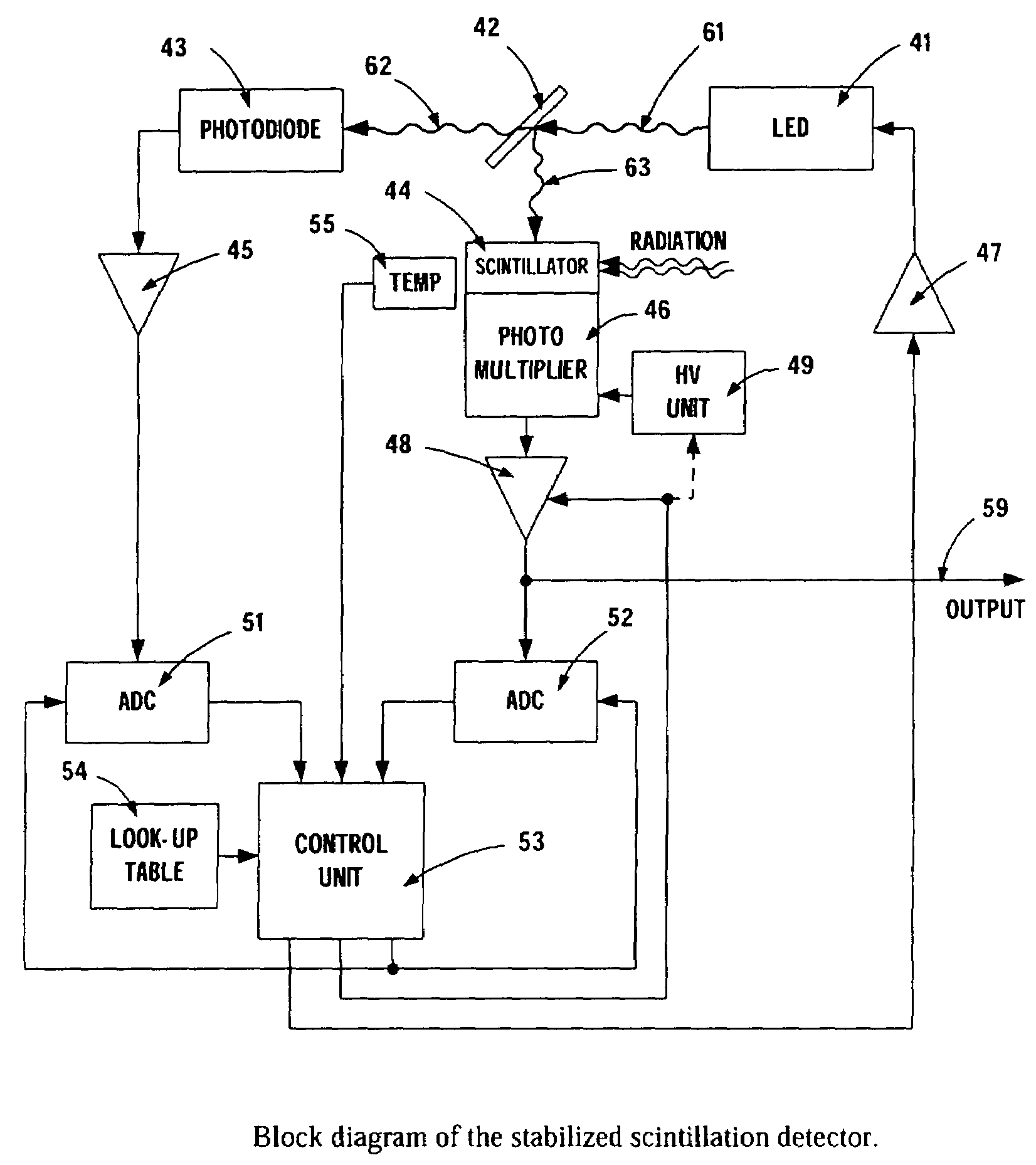
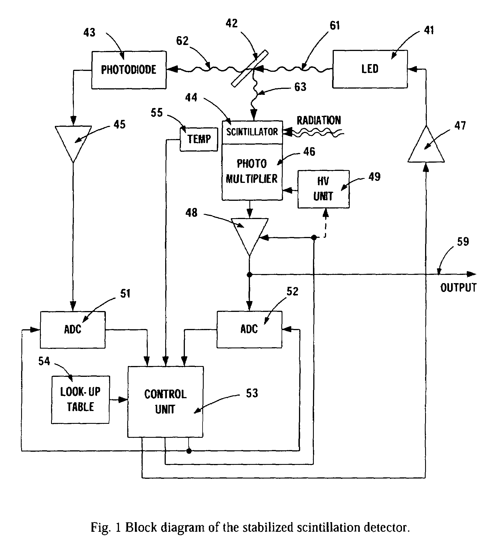
[0028]A simplified block diagram of the photomultiplier stabilizer is shown in FIG. 1. The stabilization technique uses a light source LED 41. The LED operates in pulse mode—that is, it produces periodically very short light pulses. The LED light beam 61 is split by a light splitter 42. One portion of the beam 62 illuminates a photodiode 43 and the other light beam 63 illuminates the photosensitive part of the photomultiplier 46. The photomultiplier is referred to a device with internal gain—often this is a photomultiplier tube (PMT) but also can be an avalanche photodiode, for example. The l...


PUM


Abstract

In a preferred embodiment, a stabilized scintillation detector, including: an LED that periodically produces a light pulse; a beam splitter that impinges some of the light pulse on a photodetector and on a photomultiplier; a scintillator that receives radiation and is coupled to the photomultiplier; and a control unit that receives signals from the photodetector and the photomultiplier representative of the light pulse received by the photodetector and the photomultiplier and receives a signal representative of temperature of the scintillator and outputs, in part, a signal to the photomultiplier to stabilize the photomultiplier. A method of using the scintillator is also provided.

Description

CROSS-REFERENCE TO RELATED APPLICATION[0001]Benefit is claimed of the filing date of U.S. Provisional Patent Application No. 60 / 398,096, filed Jul. 24, 2002, and titled STABILIZED SCINTILLATION DETECTOR FOR RADIATION SPECTROSCOPY.BACKGROUND OF THE INVENTION[0002]1. Field of the Invention[0003]The present invention relates to radiation spectroscopy generally and, more particularly, but not by way of limitation, to a novel stabilized scintillation detector and a method of use thereof.[0004]2. Background Art[0005]In U.S. Pat. No. 4,160,165, McCombs and Stein describe a gain stabilization circuit applicable for scintillation detectors working in current mode. The stabilization is achieved by using light emitting diode (LED) that simultaneously illuminates two photodetectors. The first photo detector is a photo-multiplier tube (PMT) that is a part of the scintillation detector. That is, the PMT photocathode is illuminated by light from both the scintillation crystal and the LED. The seco...

Claims


Application Information

Patent Timeline
Patent Type & Authority Patents(United States)
IPC IPC(8): G01T1/208
CPCG01T1/208
Inventor JORDANOV, VALENTIN T.KASTNER, MAT
Owner CANBERRA IND INC
Why Eureka
Try Eureka