Control device for electric motor

a control device and electric motor technology, applied in the direction of motor/generator/converter stopper, dynamo-electric gear control, dynamo-electric converter control, etc., can solve the problems of deteriorating control accuracy at the motor's driving under a high load condition, increasing the q-axis current further,

Active Publication Date: 2006-02-28
NISSAN MOTOR CO LTD
View PDF11 Cites 165 Cited by
  • Summary
  • Abstract
  • Description
  • Claims
  • Application Information

AI Technical Summary

Benefits of technology

[0009]The present invention is provided to improve the art described above. An object of the present invention is to provide a control device for an electric motor that enables a sensor-less operation even under a high load driving condition.

Problems solved by technology

With the delay in either errors or indication of a drive current as a start, if a q-axis current is increased due to the above characteristic feature ②, then a phase of detection is delayed, thereby causing a further increasing of the q-axis current.
As a result, when an elliptical current becomes a perfect circle due to the above characteristic feature ① and when the correlation of the characteristic feature ② approaches approximately 1 so that the long axis of an ellipse does not represent a d-axis but a current phase, the control accuracy is deteriorated at the motor's driving under a high load condition.

Method used


Image

  • Control device for electric motor
  • Control device for electric motor
  • Control device for electric motor

Examples


first embodiment

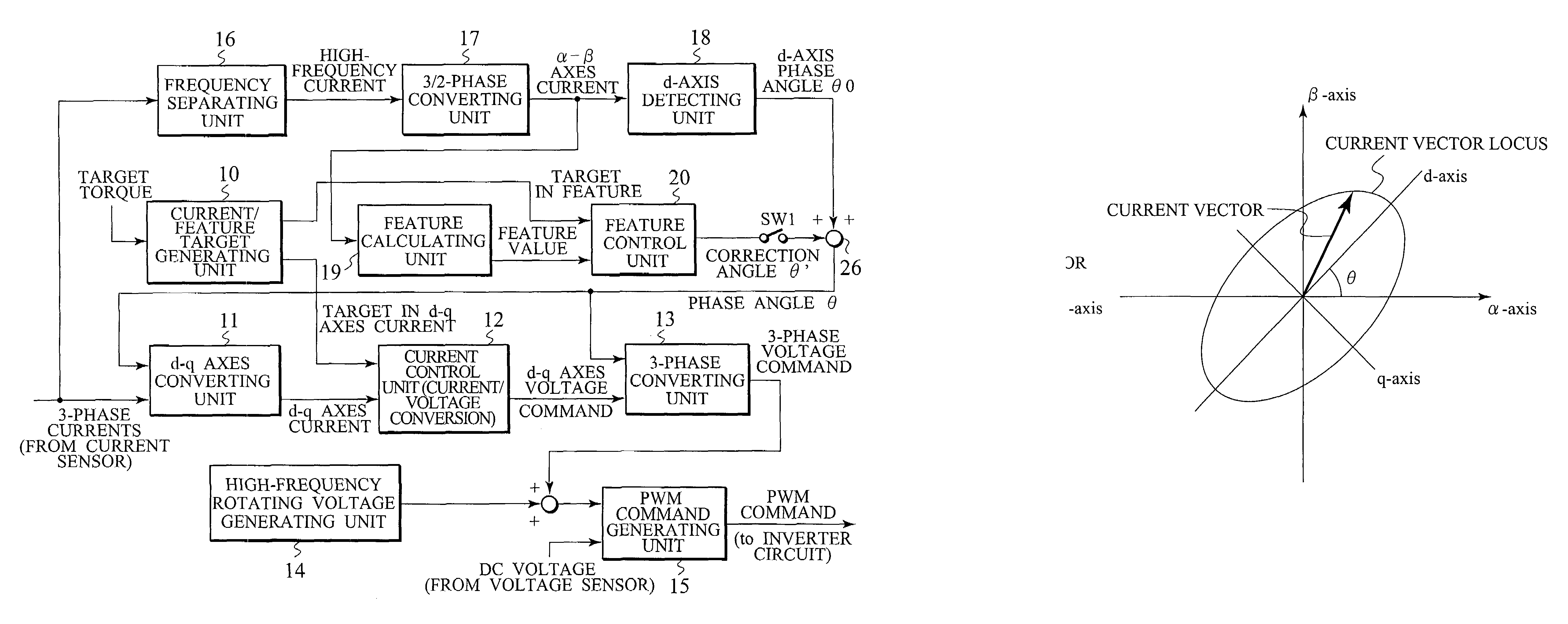
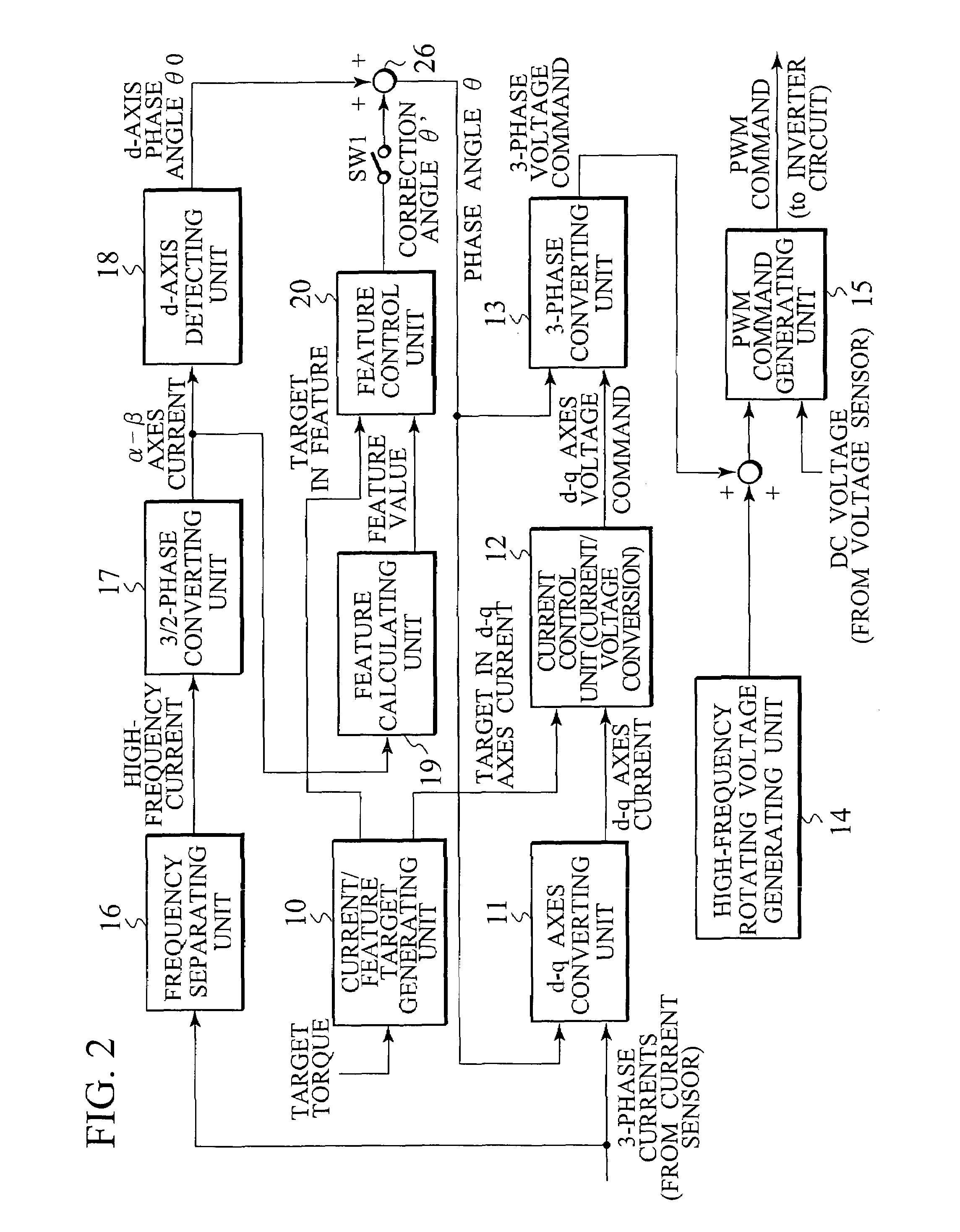
[0055]FIG. 2 is a block diagram showing the details of the control device 1, in accordance with the invention.

[0056]In FIG. 2, a current / characteristic feature target generating unit 10 generates a target value in d-axis current, a target value in q-axis current and a characterizing amount based on a target torque (e.g. manipulating amount for accelerator pedal) provided from outside. Noted that “characteristic feature” is a value based on at least one of the length of a long axis and the length of a short axis of a current vector locus. As the above value, for example, there are the length (a) of a long axis, a length (b) of a short axis, a+b, a×b, √{square root over ( )}(a2+b2), a / b, √{square root over ( )}(a2+b2)÷(a+b), etc. which will be described later in detail.

[0057]A d-axis / q-axis converting unit 11 calculates a d-axis current and a q-axis current by the three-phase currents obtained by the current sensor 4 of FIG. 1 and a phase angle θ (its details described later).

[0058]A ...

second embodiment

[0133]Next, FIG. 22 is a block diagram, showing the details of the control device 1 of FIG. 1, in accordance with the invention.

[0134]In this embodiment, when the motor is driven in a high load zone causing the magnetic saturation, only the characteristic-feature control unit 20′ detects a phase of the motor, while a d-axis phase angle θ0 from the d-axis detecting unit 18 is not used.

[0135]In this case, the characteristic-feature control unit 20′ outputs an angular speed ω′[rad / s]. Then, the angular speed ω′ is integrated to calculate a phase angle θ′ [rad] by an integrating circuit 21. That is, the characteristic-feature control unit 20′ calculates an angular speed ω′[rad / s] and corrects a phase angle by means of PI control method etc. Since the characteristic quantity has a feature of downward inclination to the right due to the current phase β, if an actual characteristic feature is larger than its target value, the detection phase is advanced (increasing of the angular speed ω′)...

third embodiment

[0146]FIG. 23 is a block diagram, showing the details of the control device 1 of FIG. 1, in accordance with the invention.

[0147]In this embodiment, an angular speed ω is employed in the calculation of a d-axis phase angle θ0 at the d-axis detecting unit 18.

[0148]In FIG. 23, the frequency separating unit 16 inputs a d-axis current and a q-axis current after conversion by the d-axis / q-axis converting unit 11 and further separates high-frequency components (high-frequency d-axis / q-axis currents) from the above currents.

[0149]At the d-axis detecting unit 18′, both amplitude and phase of the current vector are determined by detecting respective peak values and zero-cross periods of the d-axis component id and the q-axis component iq of the current vector (after separating high-frequency components) converted onto the d / q-axes. Although an angle θ between the d-axis and the long axis of an ellipse is similar to that of the above expression (1) expect to alter the members of Iα, Iβ, φiα an...


PUM


Abstract

Corresponding to a target torque, the control device calculates a target value of a feature based on at least one of the length of a long axis of a current vector locus and the length of the short axis and further superimposes a superimposed current on a drive current for the motor, the superimposed current having a frequency different from the frequency of the drive current. Further, the control device detects an actual value of the feature based on at least one of the length of a long axis of a current vector locus of the superimposed current and the length of the short axis of the same and finally detects a phase angle of the motor based on the target value and the actual value for the feature. The manipulation of a detecting phase is performed by feedback of a feature obtained by the magnitude of the superimposed current. That is, when the actual feature is more than the target value, the detecting phase is advanced. Conversely, when the actual feature is less than the target value, the detecting phase is delayed.

Description

BACKGROUND OF THE INVENTION[0001]1. Field of the Invention[0002]The present invention relates to a control device for an electric motor. More in detail, this invention relates to a sensor-less control technique for a three-phase synchronous motor equipped with permanent magnets for a rotor, which will be called as “internal permanent magnet (IPM) motor” hereinafter.[0003]2. Description of Related Art[0004]In order to control the rotating speed of an electric motor to be driven by an inverter, it is necessary to detect the positions (phase) of poles of a rotor. As a method of detecting the position of a rotor without any sensor, there is an article titled “Evaluation for estimated accuracy in the positional sensor-less field detecting method for PM (permanent magnet) motor, using current vector locus” (No. 683, at National Convention in 1994 of Society for Industrial Application, Institute of Electric Engineers). The article describes a technique to detect a long axis of current vect...

Claims


Application Information

Patent Timeline
Patent Type & Authority Patents(United States)
IPC IPC(8): H02P27/04H02P6/18H02P6/06H02P6/08H02P6/182H02P6/28H02P21/00H02P21/14H02P21/18H02P21/22H02P21/24H02P27/08
CPCH02P6/185H02P21/146H02P2207/05H02P21/18
Inventor KARIKOMI, TAKAAKI
Owner NISSAN MOTOR CO LTD
Why Eureka
Try Eureka