Multi-beam optical scanning apparatus and image forming apparatus

a multi-beam optical scanning and image forming technology, applied in the field of optical scanning apparatus, can solve the problems of deterioration in the resulting image quality, difficulty in independent control of the modulation of each light emitting source, etc., and achieve the effect of suppressing the variation in the diverging angle of the semiconductor laser array, stable beam spot size, and high resolution

Active Publication Date: 2006-02-28
RICOH KK
View PDF10 Cites 65 Cited by
  • Summary
  • Abstract
  • Description
  • Claims
  • Application Information

AI Technical Summary

Benefits of technology

[0032]Further, in the above-described multi-beam optical scanning apparatuses, the opening of the aperture may be in an ellipse shape. Thereby, a variation in optical spot diameters caused by variation in diverging angles of the semiconductor laser array is effectively suppressed, so that stable beam spots can be obtained.
[0033]According to another preferred embodiment of the present invention, an image forming apparatus is provided. The image forming apparatus includes a photoconductiv

Problems solved by technology

When a monolithic semiconductor laser array is used for a light source, if the interval between the light emitting sources of the semiconductor laser array is smaller than 10 μm, turning on and off of one light emitting source affects turning on and off of an adjacent light emitting source therm

Method used


Image

  • Multi-beam optical scanning apparatus and image forming apparatus
  • Multi-beam optical scanning apparatus and image forming apparatus
  • Multi-beam optical scanning apparatus and image forming apparatus

Examples


first embodiment

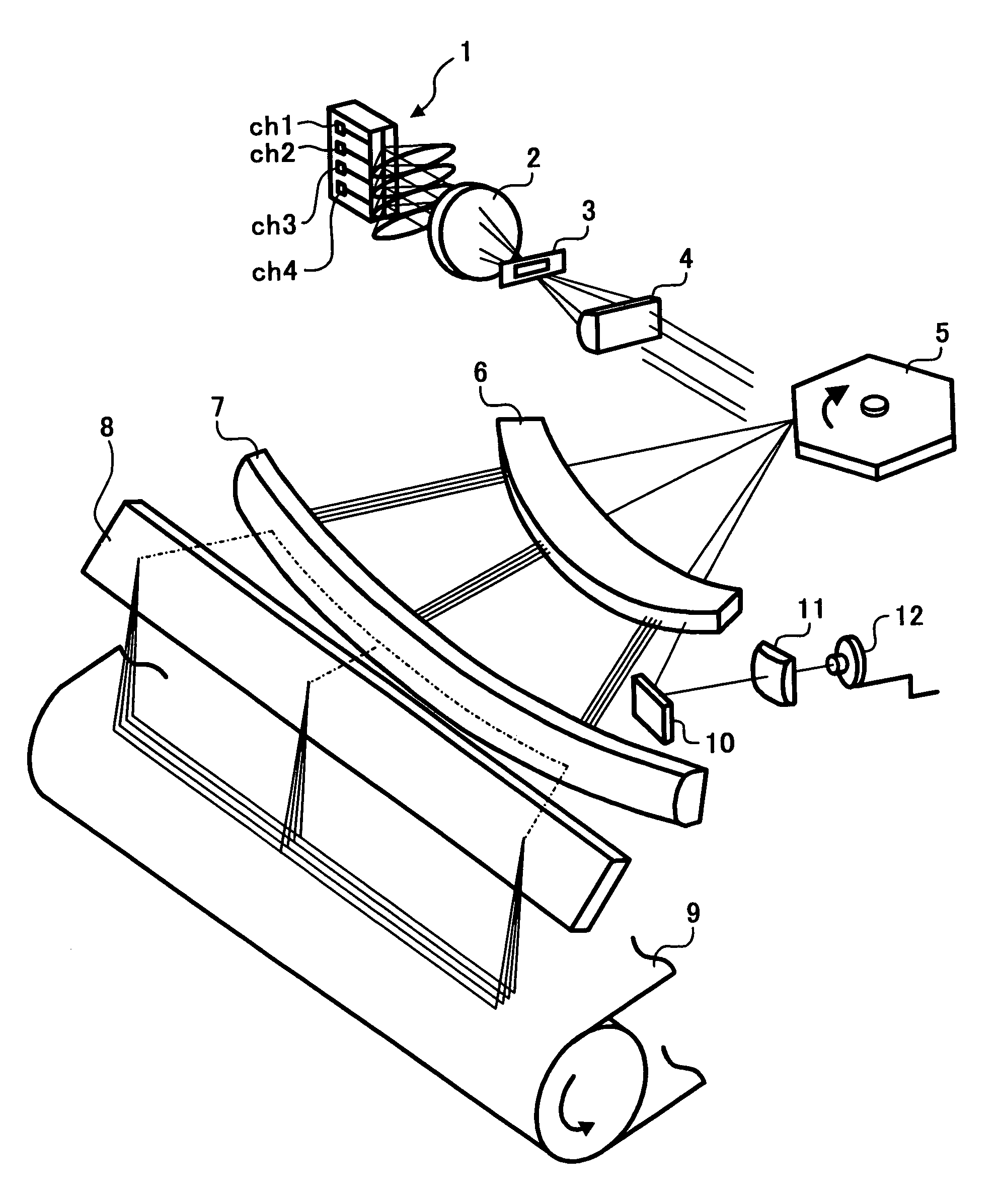
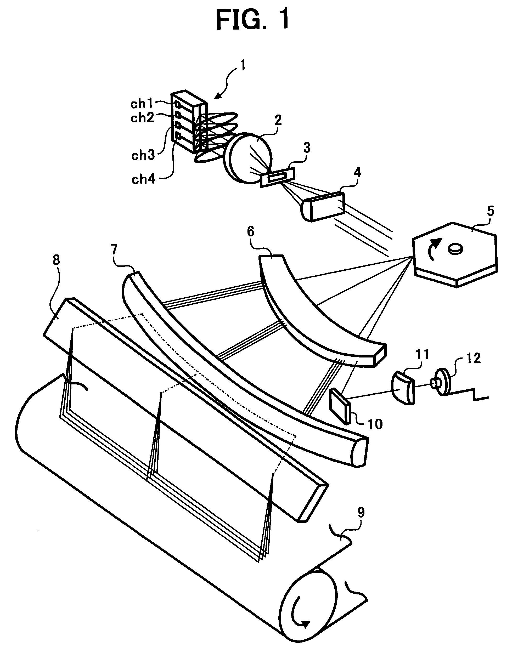
[0103]FIG. 5 schematically illustrates the construction of a scanning optical system of a multi-beam optical scanning apparatus according to the present invention. The scanning optical system is substantially the same as the one of the multi-beam optical scanning apparatus illustrated in FIG. 1. The scanning optical system includes the coupling lens 2, the aperture 3, the cylindrical lens 4, the rotating multi-faced mirror 5, the first image forming lens 6, and the second image forming lens 7. A plurality of laser optical beams emitted from the semiconductor laser array 1 launch onto the rotating multi-faced mirror 5 via the coupling lens 2, the aperture 3, and the cylindrical lens 4, and are then reflected and deflected by the rotating multi-faced mirror 5. The deflected beams are formed into beam spots on a scanning surface SS of the photoconductor 9 via the first image forming lens 6 and the second image forming lens 7. As the rotating multi-faced mirror 5 rotates, the beam spots...

second embodiment

[0150]FIG. 7 schematically illustrates the construction of a scanning optical system of the multi-beam optical scanning apparatus of FIG. 1, according to the present invention. The scanning optical system includes a coupling lens 2A, an aperture 3A, a cylindrical lens 4A, a rotating multi-faced mirror 5A, a first image forming lens 6A, and a second image forming lens 7A, which respectively correspond to the coupling lens 2, the aperture 3, the cylindrical lens 4, the rotating multi-faced mirror 5, the first image forming lens 6, and the second image forming lens 7 in FIG. 1. A plurality of laser optical beams emitted from the semiconductor laser array 1A launch onto the rotating multi-faced mirror 5A via the coupling lens 2A, the aperture 3A, and the cylindrical lens 4A, and are then reflected and deflected by the rotating multi-faced mirror 5A. The deflected beams are formed into beam spots on the scanning surface SS of the photoconductor 9A via the first image forming lens 6A and ...

third embodiment

[0199]FIG. 9 schematically illustrates the construction of a scanning optical system of the multi-beam optical scanning apparatus of FIG. 1, according to the present invention. The scanning optical system includes a coupling lens 2B, a cylindrical lens 4B, a rotating multi-faced mirror 5B, a first image forming lens 6B, 6B′, and a second image forming lens 7B, which respectively correspond to the coupling lens 2, the cylindrical lens 4, the rotating multi-faced mirror 5, the first image forming lens 6, and the second image forming lens 7 in FIG. 1. The scanning optical system further includes a beam expansion optical system 21 for the main scanning direction between the cylindrical lens 4B and the rotating multi-faced mirror 5B. A plurality of laser beams emitted from the semiconductor laser array 1B launch onto the rotating multi-faced mirror 5B via the coupling lens 2B, the aperture 3B (not illustrated in FIG. 9), the cylindrical lens 4B, and the beam expansion optical system 21, ...


PUM


Abstract

A multi-beam optical scanning apparatus includes a semiconductor laser array slanted relative to a sub-scanning direction and emitting a plurality of optical beams; a coupling lens converting a shape of each optical beam emitted from the semiconductor laser array; and an aperture with an opening having a size of Am×As, arranged after the coupling lens in a direction in which the optical beam progresses, where Am is a dimension of the opening in a main scanning direction and As is a dimension of the opening in the sub-scanning direction. When a length in the main scanning direction of a contour line defined by 1/e2 strength of a maximum strength of an optical beam at the position of the aperture is Lm, and a length in the sub-scanning direction of the contour line defined by 1/e2 strength of the maximum strength of the optical beam at the position of the aperture is Ls, the following conditional expressions are satisfied:
Am<Lm, and  (1)
Ls/Lm×0.3<As/Am<Ls/Lm×1.7.  (2)

Description

[0001]The present application claims priority and contains subject matter related to Japanese Patent Application No. 2002-230669 filed in the Japanese Patent Office on Aug. 7, 2002, and the entire contents of which are hereby incorporated by reference.BACKGROUND OF THE INVENTION[0002]1. Field of the Invention[0003]The present invention relates to an optical scanning apparatus for use in image forming apparatuses such as digital copiers and laser printers, and in more particular relates to a multi-beam optical scanning apparatus simultaneously scanning a plurality of scanning lines, and using a semiconductor laser array as a light source in which light emitting sources are arranged in a row, and an image forming apparatus using the multi-beam optical scanning apparatus.[0004]2. Discussion of the Background[0005]Optical scanning apparatuses are used in image forming apparatuses such as digital copiers and laser printers and are widely known. Recently, in these optical scanning apparat...

Claims


Application Information

Patent Timeline
IPC IPC(8): B41J27/00B41J2/44B41J2/47G02B26/10H04N1/113
CPCB41J2/473
Inventor SAKAI, KOHJIAOKI, MAGANEHAYASHI, YOSHINORISUZUKI, SEIZOATSUUMI, HIROMICHI
Owner RICOH KK
Why Eureka
Try Eureka