Planar light wave circuit and optical performance monitoring module using the same

a technology of optical performance monitoring and light wave circuit, applied in the field of optical communication system, can solve the problems of not providing a means or method capable of measuring polarization characteristics, affecting the spread of pulses, and becoming a big problem for light transmission

Inactive Publication Date: 2006-02-28
SAMSUNG ELECTRONICS CO LTD
View PDF3 Cites 9 Cited by
  • Summary
  • Abstract
  • Description
  • Claims
  • Application Information

AI Technical Summary

Benefits of technology

[0007]Accordingly, the present invention was developed to solve the above-mentioned problems associated with the prior art. One aspect of the present invention is to provide an optical-perfor...

Problems solved by technology

Although a conventional OPM can measure various characteristics of an inputted optical signal, it does not provide a means or method that is capable of measuring a polarization characteristic.
When an optical signal has a bad polarization characteristic, a polarization mode dispersion (PMD) may develop thus becoming a big problem to light transmission.
In the polarization ...

Method used


Image

  • Planar light wave circuit and optical performance monitoring module using the same
  • Planar light wave circuit and optical performance monitoring module using the same
  • Planar light wave circuit and optical performance monitoring module using the same

Examples


Embodiment Construction

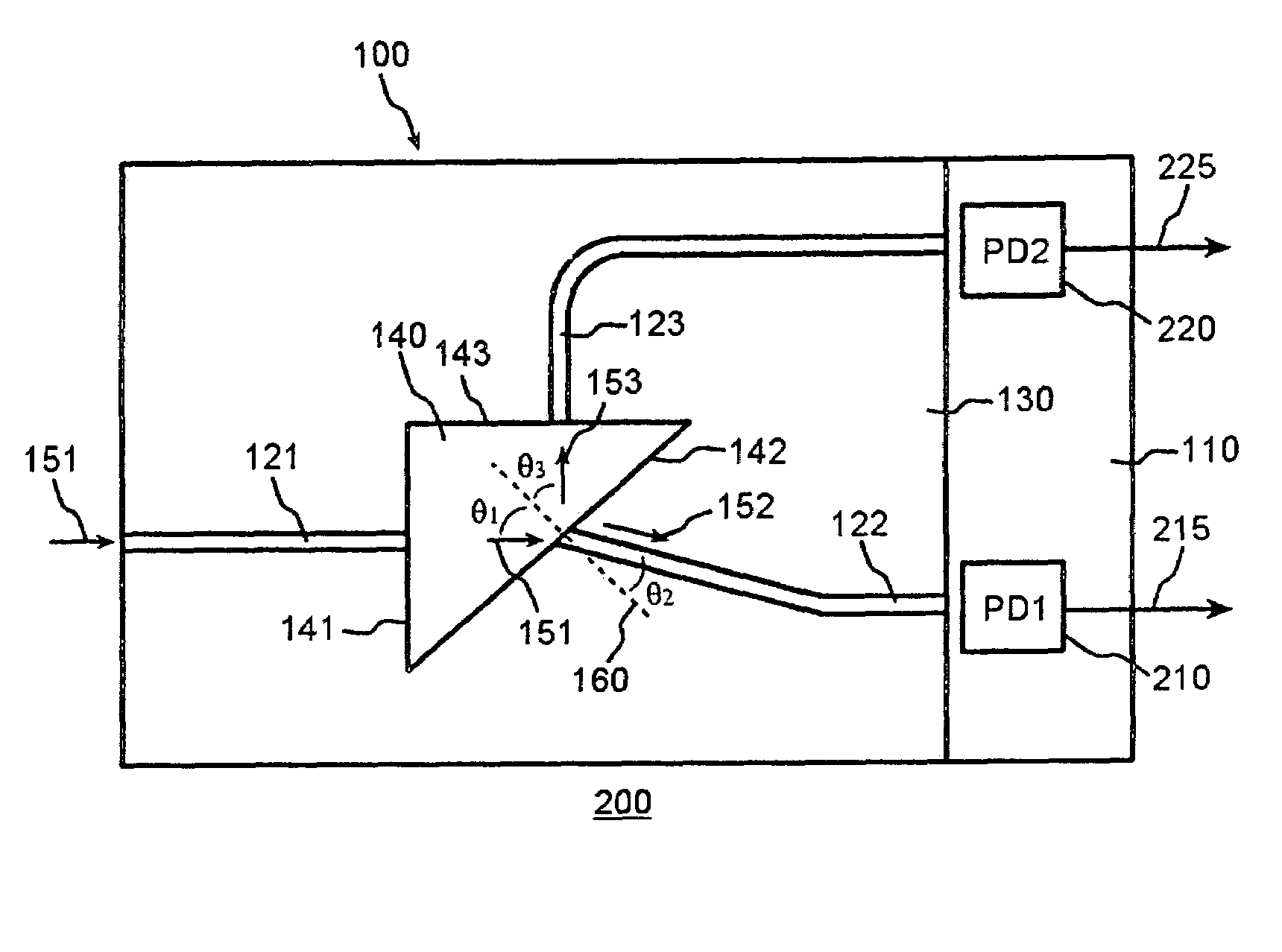
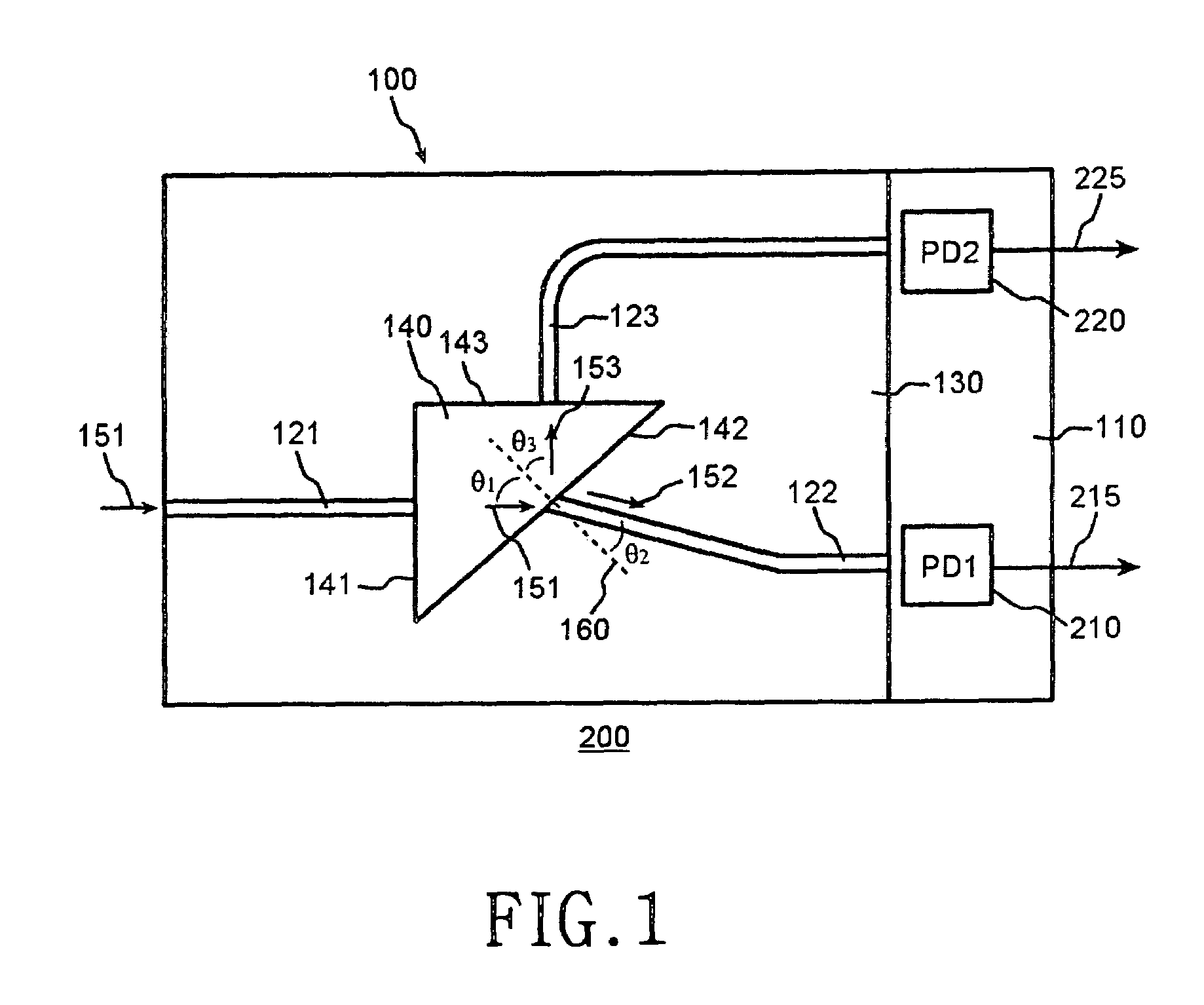
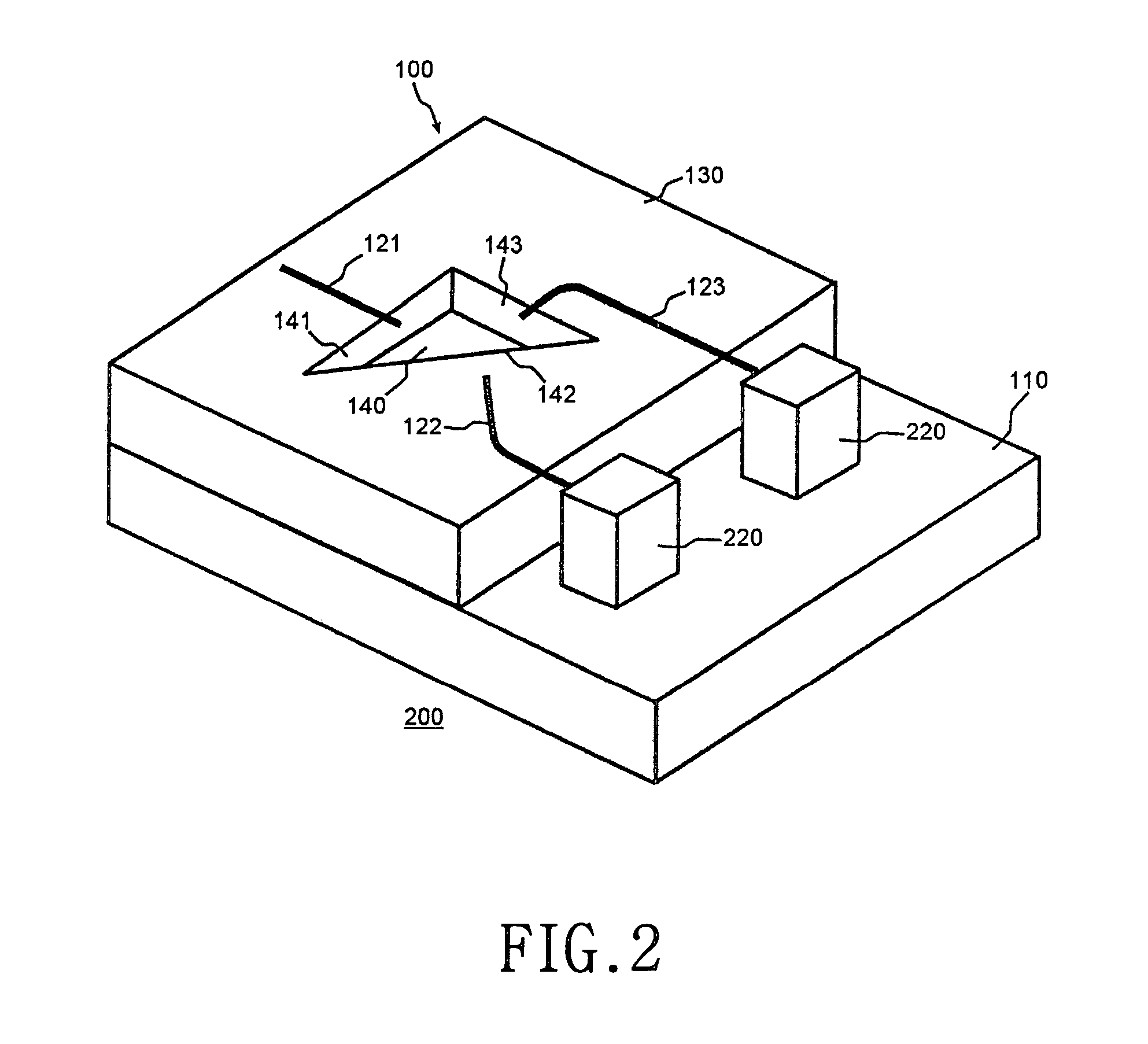
[0015]A preferred embodiment of the present invention will be described with reference to the accompanying drawings. For the purpose of clarity and simplicity, a detailed description of known functions and configurations will be omitted herein. FIG. 1 is a block diagram showing a construction of an optical-performance-monitoring module according to a preferred embodiment of the present invention and FIG. 2 is a perspective view showing the optical-performance-monitoring module shown in FIG. 1.

[0016]The optical-performance-monitoring module 200 includes a planar light wave circuit 100 and first and second detectors 210 and 220.

[0017]The planar light wave circuit 100 is formed on a semiconductor substrate 110 and includes a first to a third waveguide 121 to 123 with a relatively high index of refraction and a clad 130 surrounding the first to the third waveguide 121 to 123. In order to minimize optical coupling loss occurring when an optical signal is inputted to the first to the thir...


PUM


Abstract

A planar light wave circuit is disclosed, which comprises: a first waveguide for receiving optical signals from an outside; a second waveguide having a first end surface and a second end surface, so that lights outputted from the first waveguide are partially reflected by the first end surface and are partially incidented into the first end surface and then outputted through the second end surface; a third waveguide for receiving the light reflected by the first end surface; and a common region bordering each end surface of the first to the third waveguides and having an index of refraction different from an index of refraction of the second waveguide.

Description

CLAIM OF PRIORITY[0001]This application claims priority to an application entitled “Planar light wave circuit and optical performance monitoring module using the same,” filed in the Korean Intellectual Property Office on Jun. 4, 2003 and assigned Serial No. 2003-35962, the contents of which are hereby incorporated by reference.BACKGROUND OF THE INVENTION[0002]1. Field of the Invention[0003]The present invention relates to an optical communication system, particularly to an apparatus for monitoring an optical signal passing through the optical communication system.[0004]2. Description of the Related Art[0005]In an optical communication system with a wavelength division multiplexing (WDM) method, an optical signal passing through the optical fiber generally includes a plurality of channels with wavelengths different from each other. In order to monitor certain characteristics, such as the optical signal-to-noise ratio (OSNR), wavelength and power with respect to each channel, the opti...

Claims


Application Information

Patent Timeline
IPC IPC(8): G02B6/26G02B6/42G02B6/12G02B6/122G02B6/126G02B6/34
CPCG02B6/12007G02B6/126H04B10/07955H04B10/077G02B6/29385G02B6/4213G02B6/4215G02B6/4286G02B6/12
Inventor LEE, JOO-HOONKIM, DONG-SUKIM, KYOUNG-YOUM
Owner SAMSUNG ELECTRONICS CO LTD
Why Eureka
Try Eureka