Gear assembly having noise-reduction structure and power take-off unit therewith

a technology of noise reduction structure and power take-off unit, which is applied in the direction of gearing, hoisting equipment, transportation and packaging, etc., can solve the problems of loosely woven gears rumbling against one another, generating undesirable noise, and bothering persons located in the vicinity, so as to improve the noise reduction structure and reduce the amount of nois

Inactive Publication Date: 2006-03-07
PARKER INTANGIBLES LLC
View PDF14 Cites 23 Cited by
  • Summary
  • Abstract
  • Description
  • Claims
  • Application Information

AI Technical Summary

Benefits of technology

[0007]This invention relates to an improved noise-reduction structure for use with a meshing gear assembly. The noise-reduction structure includes a toothed disk that is supported on a first gear, such as on an input gear of a power take-off unit. The toothed disk is supported on the first gear in such a manner as to be frictionally engaged therewith, but rotationally and radially movable relative thereto. The circumferential width of each tooth formed on the toothed disk is preferably larger than the circumferential width of each tooth formed on the first gear when measured at the operating pitch diameter thereof. Also, the outer diameter of the toothed disk can be larger than the outer diameter of the first gear. The first gear and the toothed disk mesh with a second gear, such as a transmission gear, such that as the second gear rotates, the toothed disk and the first gear also rotate. However, the toothed disk and the first gear rotate at different speeds because the difference in the number of teeth formed thereon. Because the teeth formed on the toothed disk have a larger circumferential thickness and a larger outer diameter than the teeth formed on the first gear, a tight meshing engagement with the second gear is provided. This tight meshing engagement, in combination with the frictional engagement of the toothed disk with the first gear, takes up backlash between the first gear and the second gear, thereby reducing the amount of noise that is generated during operation of the meshing gear assembly.

Problems solved by technology

When a typical power take-off unit is operated, it often generates an undesirable amount of noise.
Such noise usually results from the combination of torsional vibrations that are generated from the vehicle engine to the power take-off unit and backlash or looseness that typically exists between the meshing gears contained within the power take-off unit.
It has been found that such torsional vibrations can cause the loosely meshing gears to rattle against one another as they are rotatably driven during use.
Although the generation of such noise does not usually adversely affect the operation of the power take-off unit, it can be quite bothersome to persons that are located in the vicinity.
However, such known noise-reduction structures have been found to be deficient for various reasons.

Method used


Image

  • Gear assembly having noise-reduction structure and power take-off unit therewith
  • Gear assembly having noise-reduction structure and power take-off unit therewith
  • Gear assembly having noise-reduction structure and power take-off unit therewith

Examples


Embodiment Construction

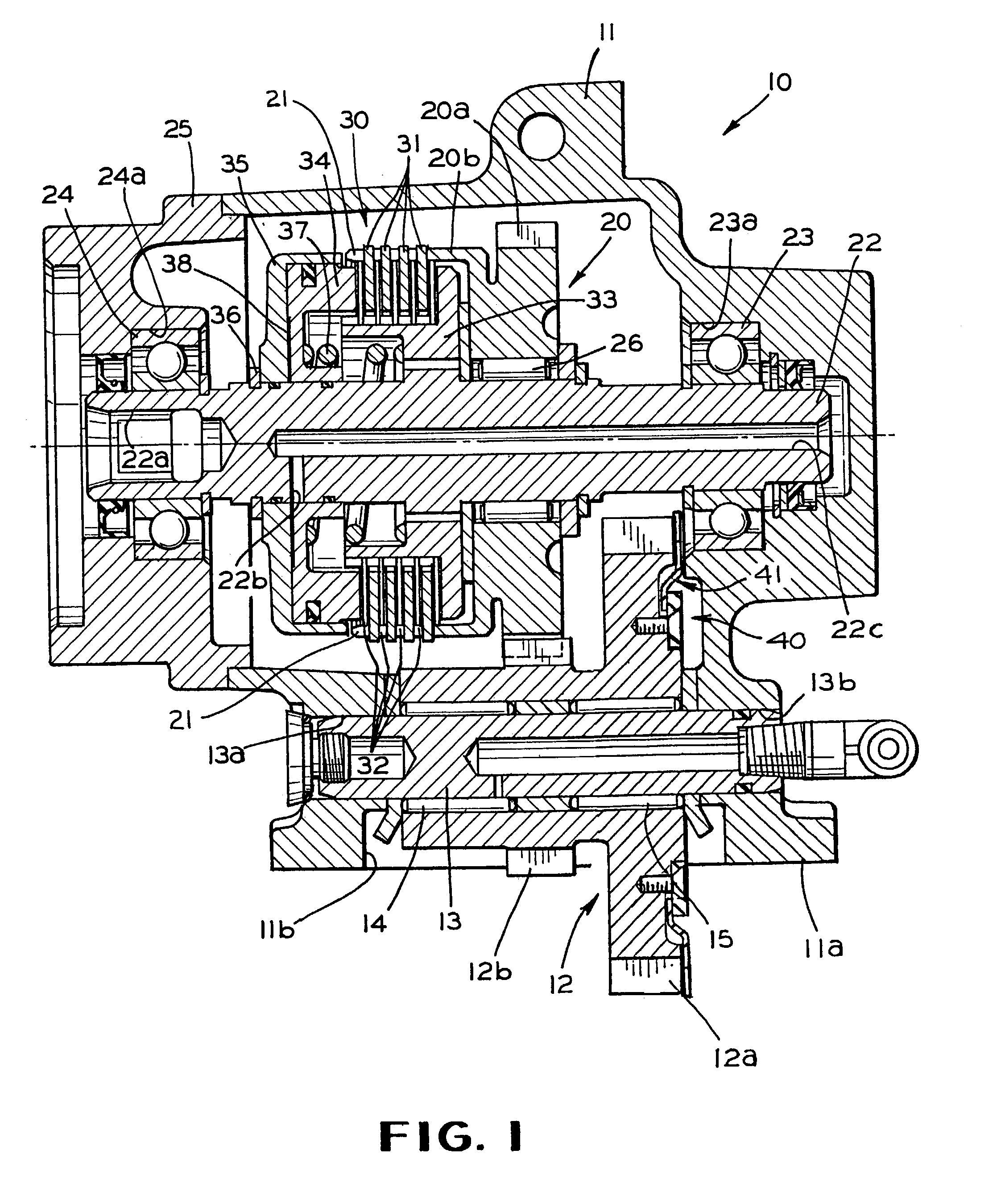
[0012]Referring now to the drawings, there is illustrated in FIG. 1 a power take-off unit, indicated generally at 10, in accordance with this invention. The illustrated power take-off unit 10 is, in large measure, conventional in the art and is intended merely to illustrate one environment in which this invention may be used. Thus, the scope of this invention is not intended to be limited for use with the specific structure for the power take-off unit 10 illustrated in FIG. 1 or with power take-off units in general. On the contrary, as will become apparent below, this invention may be used in any desired environment for the purposes described below.

[0013]The illustrated power take-off unit 10 includes a rigid hollow housing 11 having a mounting surface 11a formed thereon. An opening 11b is formed through the mounting surface 11a for a purpose that will be described below. An input gear 12 is rotatably supported in the housing 11 of the power take-off unit 10. To accomplish this, an ...


PUM


Abstract

A meshing gear assembly includes a toothed disk that is supported on a first gear so as to be frictionally engaged therewith, but rotationally and radially movable relative thereto. The circumferential width of each tooth formed on the toothed disk is preferably larger than the circumferential width of each tooth formed on the first gear, and the outer diameter of the toothed disk can be larger than the outer diameter of the first gear. The first gear and the toothed disk mesh with a second gear such that as the second gear rotates, the toothed disk and the first gear also rotate. However, the toothed disk and the first gear rotate at different speeds because the difference in the number of teeth formed thereon. Because the teeth formed on the toothed disk have a larger circumferential thickness and a larger outer diameter than the teeth formed on the first gear, a tight meshing engagement with the second gear is provided. This tight meshing engagement, in combination with the frictional engagement of the toothed disk with the first gear, takes up backlash between the first gear and the second gear.

Description

CROSS REFERENCE TO RELATED APPLICATION[0001]This application claims the benefit of U.S. Provisional Application No. 60 / 341,446, filed Dec. 18, 2001, the disclosure of which is incorporated herein by reference.BACKGROUND OF THE INVENTION[0002]This invention relates in general to noise-reduction structures for use with meshing gear assemblies. In particularly, this invention relates to an improved noise-reduction structure for use with a meshing gear assembly in a power take-off unit.[0003]Power take-off units are well known mechanical devices that are commonly used in conjunction with sources of rotational energy, such as vehicle engines and transmissions, for selectively providing power to one or more rotatably driven accessories. For example, power take-off units are commonly used in a variety of industrial and agricultural vehicles for operating hydraulic pumps that, in turn, operate hydraulically driven accessories, such as plows, trash compactors, lifting mechanisms, winches, an...

Claims


Application Information

Patent Timeline
Patent Type & Authority Patents(United States)
IPC IPC(8): F16H55/18B60K17/28F16H55/17F16H57/00
CPCF16H55/18F16H57/0006B60K17/28Y10T74/19679Y10T74/19623Y10T74/19898Y10T74/19963Y10T74/19242
Inventor ALLEN, MARK A.KRUSE, RANDY P.SHOPE, MATTHEW W.
Owner PARKER INTANGIBLES LLC
Why Eureka
Try Eureka