
Missile system for breaching reinforced concrete barriers utilizing hinged explosively formed projectile warheads

Inactive Publication Date: 2006-03-07
UNITED STATES OF AMERICA THE AS REPRESENTED BY THE SEC OF THE ARMY
View PDF6 Cites 17 Cited by
  • Summary
  • Abstract
  • Description
  • Claims
  • Application Information

AI Technical Summary

Benefits of technology

[0007]A hinged explosively formed projectile warhead system (referred to herein as “the system” or “the present system”) eliminates exposure of soldiers to harm in wall breaching operations by providing a breaching mechanism that can be deployed at safe distances. Such requirements typically exist in Military Operations in Urban Terrain (MOUT) environments where the infantry soldier plays a key role. The present system simultaneously breaches a man-sized hole and removes one or more rows of rebar in reinforced concrete structures or barriers. The present system employs both a missile system and an explosively formed projectile warhead technology delivered to the target from a tube launched platform.
[0010]In an embodiment, the warhead arms are released from the missile body prior to impact at a reinforced concrete target. In a further embodiment, release of the warhead arms initiates a time delay fuzing mechanism for the explosives in the warhead arms. One advantage of this embodiment entails the capability of the warhead to form a long non-bifurcating wedge shaped penetrator that covers a wide area of the target. By utilizing multiple warheads, large holes are able to be breached that allows access for infantrymen to pass through.

Problems solved by technology

This manual removal of rebar is a lengthy process during which the soldier is exposed to harm.
The need for such a system has heretofore remained unsatisfied.

Method used


Image

  • Missile system for breaching reinforced concrete barriers utilizing hinged explosively formed projectile warheads
  • Missile system for breaching reinforced concrete barriers utilizing hinged explosively formed projectile warheads
  • Missile system for breaching reinforced concrete barriers utilizing hinged explosively formed projectile warheads

Examples


Embodiment Construction

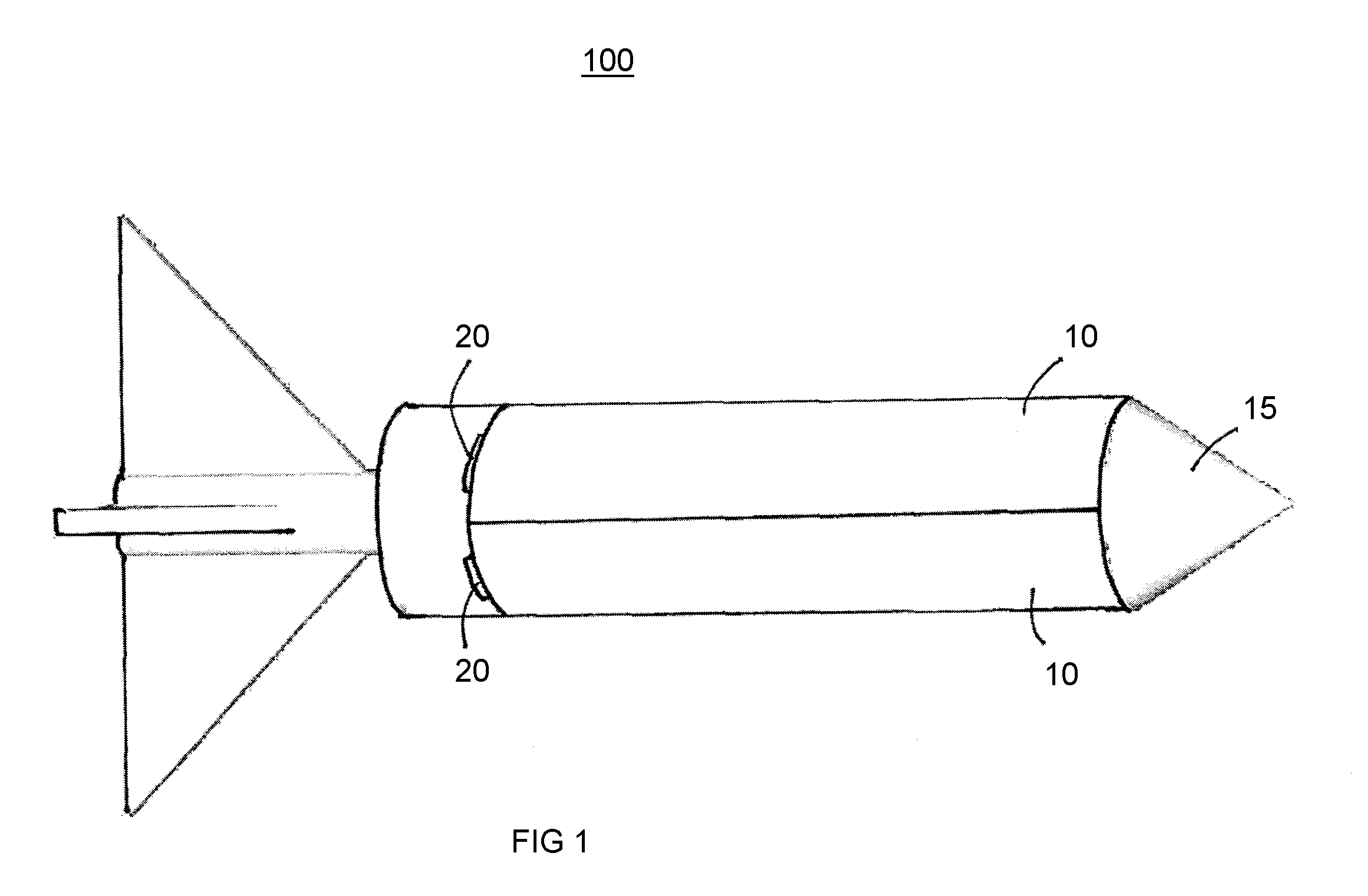
[0016]FIG. 1 (FIGS. 1A, 1B) illustrates an exemplary hinged explosively formed projectile warhead missile system 100 (referenced herein as missile system 100) comprising a set of hinged explosively formed warheads 10 (referenced herein as warheads 10), a missile body 15, and hinges 20. The warheads 10 are attached to the aft end of the missile body 15 by means of hinges 20. When detonated, warheads 10 form explosively formed projectiles. Known or available explosively formed projectile techniques can be used to practice the invention. For further details about explosively formed projectile warheads, reference is made, for example, to the U.S. Pat. No. 6,619,210.

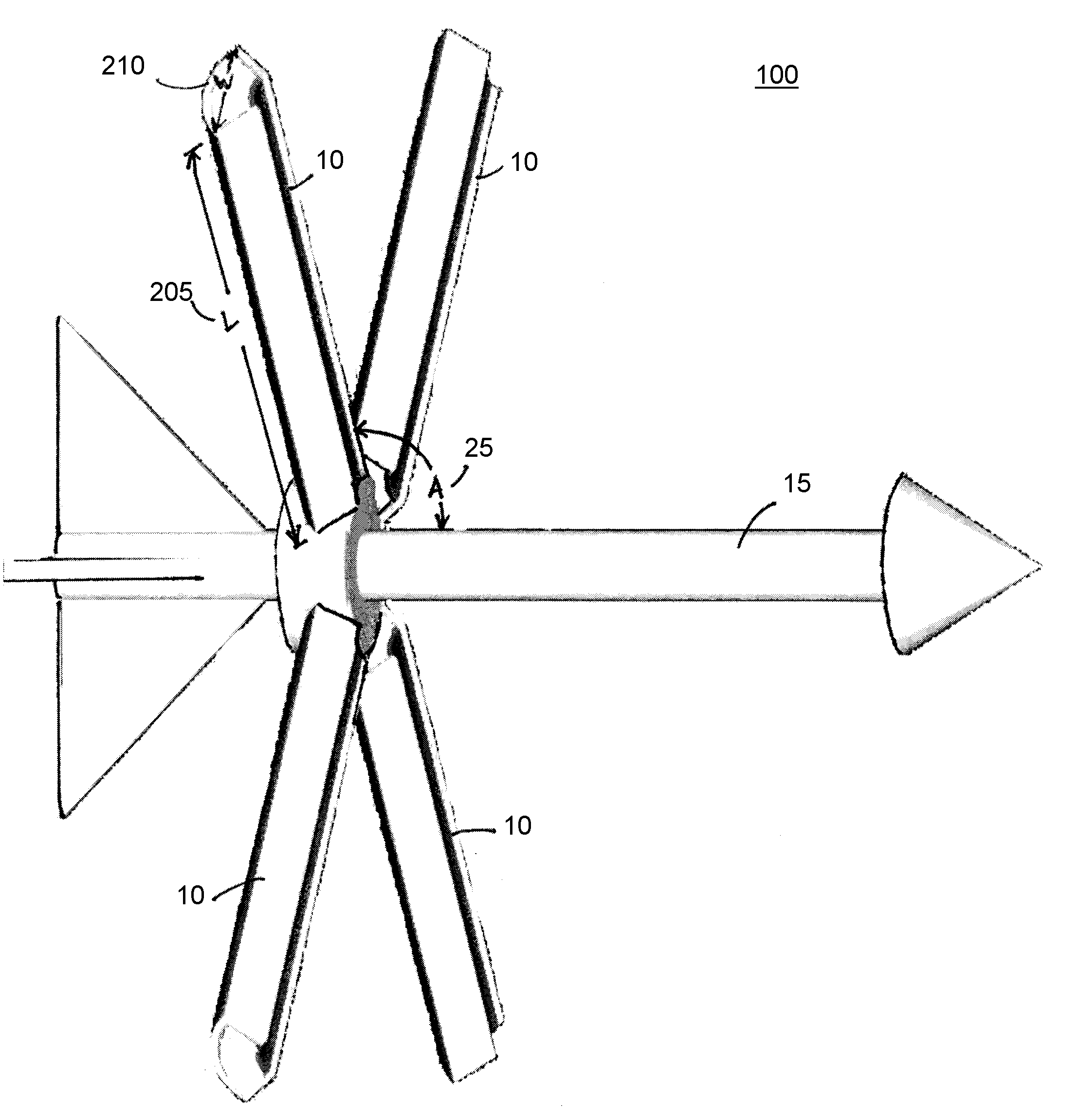
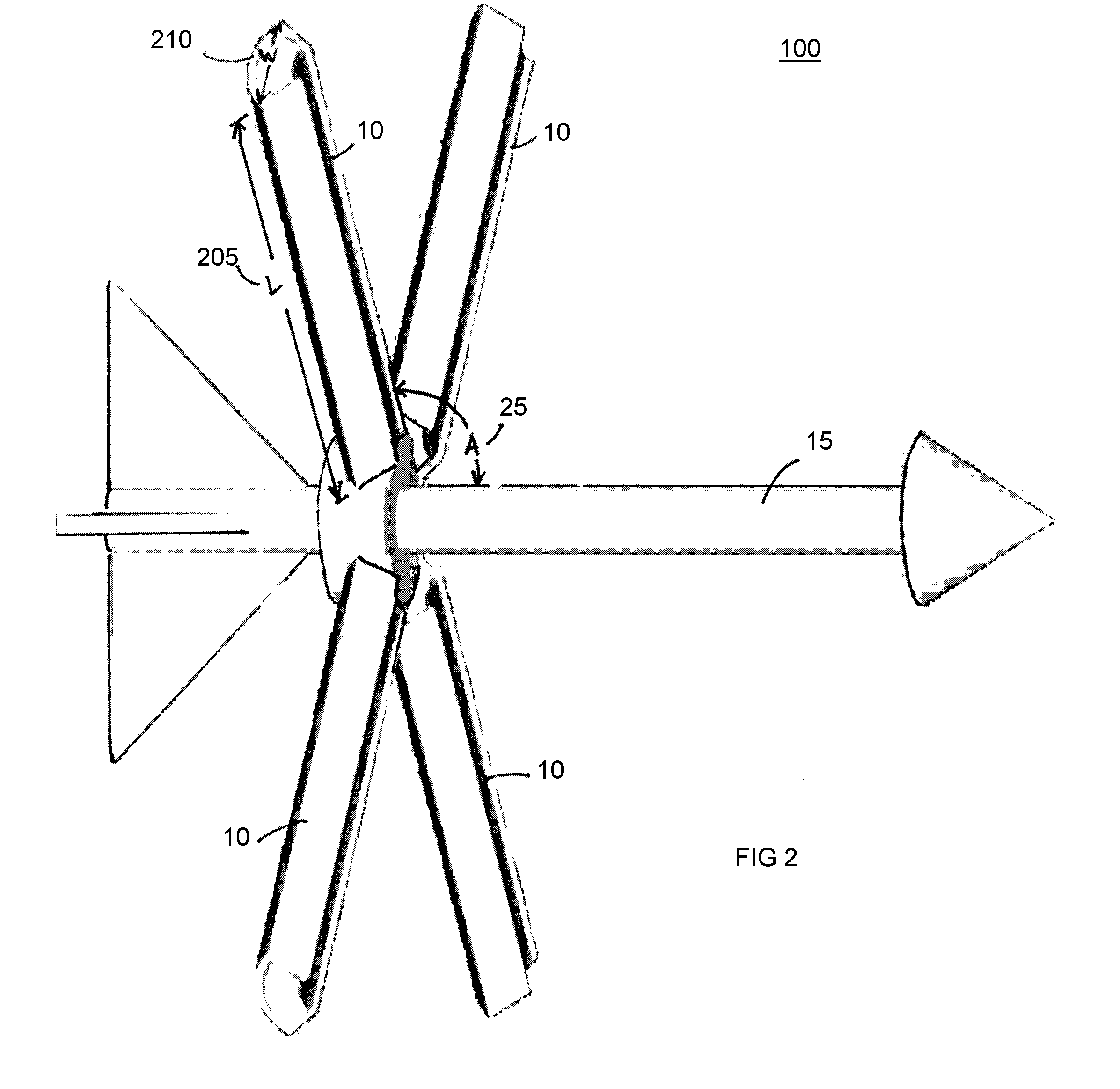
[0017]The warheads 10 are initially folded up against the missile body 15 as illustrated in FIG. 1. Missile system 100 is launched from a tube platform at a very low spin rate to induce stabilization during flight. After launch, the warheads 10 fold out at a hinge angle A, 25, from the forward section of the missile body 15, ...


PUM


Abstract

A hinged explosively formed projectile warhead system eliminates exposure of soldiers to harm in wall breaching operations by providing a lethal mechanism that can be deployed at safe distances, simultaneously breaching a man-sized hole and removing one or more rows of rebar in reinforced concrete structures or barriers. The warhead system employs both a missile system and explosively formed projectile warhead technology delivered to the target from a tube launched platform. A set of warhead arms is attached to the aft end of a missile body by means of a set of hinges. The warhead arms are initially folded against the missile body. After launch of the warhead system, the warhead arms fold away from the missile body. The angle at which the warhead arms are folded from the missile body determines the area of a hole breached by the warhead system in a reinforced concrete target.

Description

FEDERAL RESEARCH STATEMENT[0001]The inventions described herein may be manufactured, used and licensed by or for the U.S. Government for U.S. Government purposes.BACKGROUND OF INVENTION[0002]1. Field of the Invention[0003]The present invention generally relates to the field of ballistics and in particular to explosively formed projectiles. More specifically, the present invention pertains to a projectile utilizing explosively formed projectile warheads on hinged arms to breach a reinforced concrete barrier.[0004]2. Background of the Invention[0005]A continuing need in the Army is the ability to effectively breach man-sized holes in reinforced concrete barriers or walls. A conventional approach to breaching man-sized holes utilizes demolition or bulk explosive charges that are hand emplaced and detonated on the target. Another conventional approach to breaching man-sized holes utilizes explosively formed projectiles. The explosively formed projectile is created by using an explosive ...

Claims


Application Information

Patent Timeline
IPC IPC(8): F42B12/06
CPCF42B12/10F42B12/60F42B12/12F42B12/105
Inventor FONG, RICHARDNG, WILLIAMTHOMPSON, LAMAR
Owner UNITED STATES OF AMERICA THE AS REPRESENTED BY THE SEC OF THE ARMY
Learn More