
Braking system for a personal watercraft

a technology for braking systems and watercraft, which is applied in the direction of marine propulsion, special-purpose vessels, vessel construction, etc., can solve the problems of not providing satisfactory means for braking the pwc, the difficulty of pwc being notoriously difficult to brake and control, and the increase in the risk of dangerous accidents involving such watercra

Inactive Publication Date: 2006-03-07
BOOTES TODD +1
View PDF13 Cites 37 Cited by
  • Summary
  • Abstract
  • Description
  • Claims
  • Application Information

AI Technical Summary

Benefits of technology

[0005]It is therefore an object of the present invention to provide a braking system for a personal watercraft (PWC) which enables braking of the PWC to be performed quickly, safely and reliably.
[0006]It is a further object of this invention to provide a PWC braking system that allows the operator of the PWC to brake the PWC quickly enough to avoid dangerous or risky situations, and especially damaging and potentially deadly collisions.
[0007]It is a further object of this invention to provide a PWC braking system that operates wholly independently of the vessel's steering system so that improved, custom braking and control are achieved.
[0008]It is a further object of this invention to provide a PWC braking system that allows the PWC to be effectively braked without having to reduce propulsion and therefore PWC control.
[0009]It is a further object of this invention to provide a PWC braking system that avoids placing undue forces and stress upon the jet nozzle of the PWC.
[0010]It is a further object of this invention to provide a PWC braking system that significantly improves PWC operating safety.

Problems solved by technology

At the same time, the risk of dangerous accidents involving such watercraft has likewise increased.
Personal watercraft (PWC) are notoriously difficult to brake and control.
Currently, no satisfactory means are provided for braking the PWC.
This technique is far from satisfactory.
For one thing, when the PWC is operating at a high speed, it can take too long for the vessel to slow to a stop.
This obviously subjects the PWC and its rider(s) to the risk of a deadly collision with objects in the water that are too close to avoid.
This problem is complicated because most personal watercraft are able to properly steer only when operated under full throttle.
Prior attempts to achieve improved PWC braking have been generally unsuccessful.
Reversing operation of the jet nozzle puts enormous and potentially damaging strain upon the nozzle.

Method used


Image

  • Braking system for a personal watercraft
  • Braking system for a personal watercraft
  • Braking system for a personal watercraft

Examples


Embodiment Construction

[0013]Other objects, features and advantages will occur from the following description of a preferred embodiment and the accompanying drawings, in which:

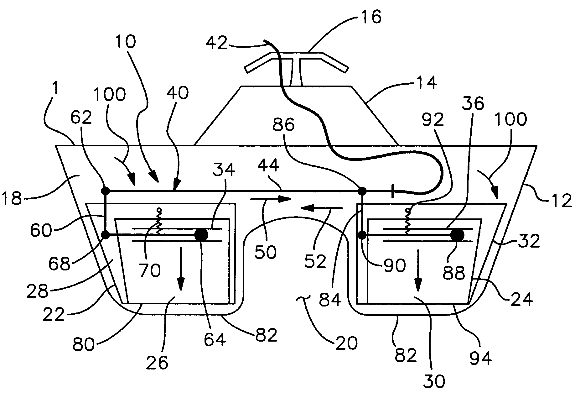
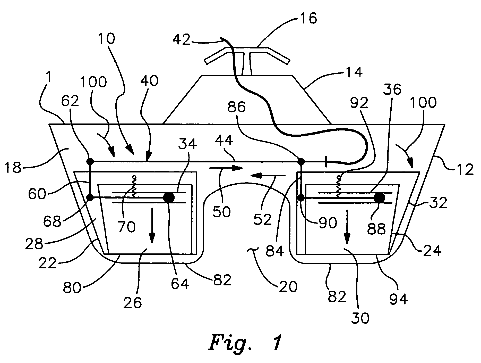
[0014]FIG. 1 is a schematic view of a personal watercraft (PWC) employing a braking system in accordance with this invention;

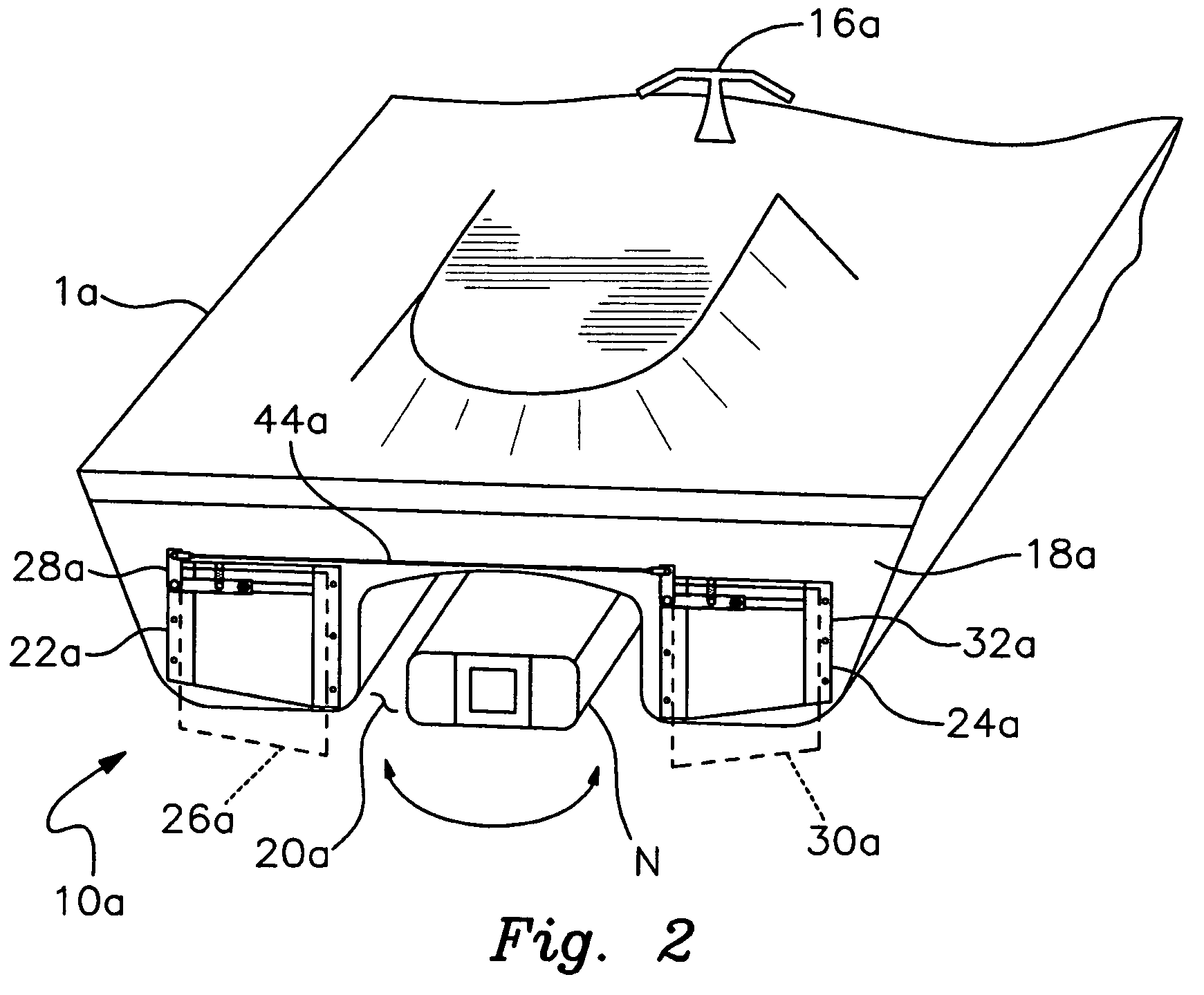
[0015]FIG. 2 is a perspective view of the stern of a PWC with a preferred version of the braking system of this invention mounted to the transom;

[0016]FIG. 3 is a simplified view of the hand-operated control levers, the actuator cable and the actuator bar;

[0017]FIG. 4 is a front elevational view of the left-hand brake plate as mounted in the support track and interengaged by respective linkage; and

[0018]FIG. 5 is a view similar to FIG. 4 of the right-hand brake plate as well as its slide track and associated linkage.

[0019]There is shown in FIG. 1, a personal watercraft (PWC) 1 that is equipped with a braking system 10 in accordance with this invention. It should be understood the braking system may be employed...


PUM


Abstract

A braking system for a personal watercraft includes at least one brake plate for mounting to the transom of a personal watercraft such that the jet nozzle of the watercraft is directionally adjustable independently of the braking system. The brake plate is alternatable between a nonbraking condition wherein the plate is retracted against the transom and is held completely above a lower edge of the transom, and a braking condition where the brake plate extends beyond the lower edge of the transom. A hand-controlled actuator assembly selectively alternates the brake plate between the braking and nonbraking conditions.

Description

FIELD OF THE INVENTION[0001]This invention relates to a braking system for a personal watercraft and, more particularly, to a braking system that operates independently of the principal steering system of the personal watercraft.BACKGROUND OF THE INVENTION[0002]Personal watercraft have become increasingly popular in recent years. At the same time, the risk of dangerous accidents involving such watercraft has likewise increased. Personal watercraft (PWC) are notoriously difficult to brake and control. In most cases, control or steering is achieved by the jet nozzle which expels pressurized water to propel the PWC. Operator controls allow the user to direct the jet nozzle as needed to accomplish desired turning or steering.[0003]Currently, no satisfactory means are provided for braking the PWC. Auxiliary braking mechanisms are rarely, if ever, utilized. Instead, the throttle must be operated to reduce propulsion so that the PWC will gradually slow. This technique is far from satisfact...

Claims


Application Information

Patent Timeline
IPC IPC(8): B63H25/48
CPCB63H25/44
Inventor BOOTES, TODD
Owner BOOTES TODD
Learn More