Apparatus and method for humidification of inspired gases

a technology of inspired gas and apparatus, which is applied in the direction of mechanical apparatus, valves, respirators, etc., can solve the problems of moisture accumulation within, and achieve the effects of saving millions of gallons of water per year, saving patient costs, and efficient utilization and conservation of energy resources

Inactive Publication Date: 2006-03-07
DAUGHERTY ROGER +1
View PDF38 Cites 9 Cited by
  • Summary
  • Abstract
  • Description
  • Claims
  • Application Information

AI Technical Summary

Benefits of technology

[0024]Accordingly, a feature and advantage of the present invention is its ability to humidify oxygen gas via a novel and non-obvious apparatus and method.
[0025]A feature and advantage of the present invention is its novel reverse flow adapter.
[0026]A feature and advantage of the present invention is its ability to humidify oxygen gas via use of condensed water from expiratory gases that accumulate within the expiratory tube of a unilimb breathing circuit.
[0027]A feature and advantage of the present invention is its ability to effectively eliminate prior art methods of oxygen gas humidification that depend upon the wasteful utilization of bottles of sterile water, other corrugated tubing, nebulizer adapters and excess consumption of oxygen gas.
[0028]A feature and advantage of the present invention is its ability to materially contribute to the environmental restoration and / or maintenance of basic life-sustaining natural elements by eliminating the use of bottles of sterile water for oxygen gas humidification, thus effectively saving millions of gallons of water per year.
[0029]A feature and advantage of the present invention is its ability to materially contribute to the more efficient utilization and conservation of energy resources by conserving valuable petroleum resources that would otherwise be utilized to manufacture plastic corrugated tubing, plastic bottles for containing sterile water, and plastic nebulizer adapters, elements crucial to implementation of prior art methods of inspired gas humidification.

Problems solved by technology

As a result of the temperature differential between the inspiratory and expiratory gases, moisture carried within the expiratory gases begins to condense within the corrugations of the expiratory tube, resulting in accumulation of moisture therewithin.

Method used


Image

  • Apparatus and method for humidification of inspired gases
  • Apparatus and method for humidification of inspired gases
  • Apparatus and method for humidification of inspired gases

Examples


Embodiment Construction

[0045]In describing the preferred and selected alternate embodiments of the present invention, as illustrated in FIGS. 1–7, specific terminology is employed for the sake of clarity. The invention, however, is not intended to be limited to the specific terminology so selected, and it is to be understood that each specific element includes all technical equivalents that operate in a similar manner to accomplish similar functions.

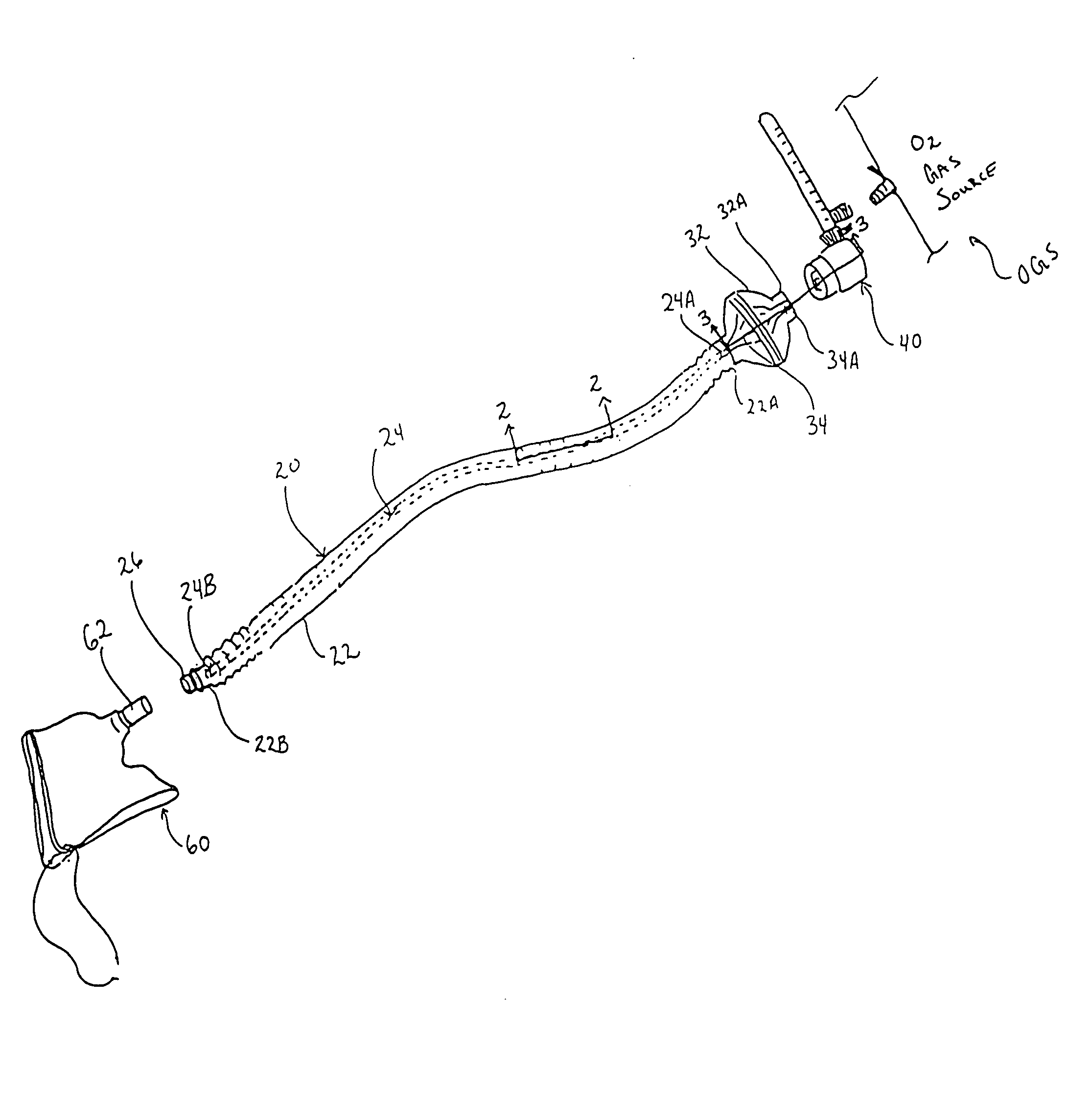
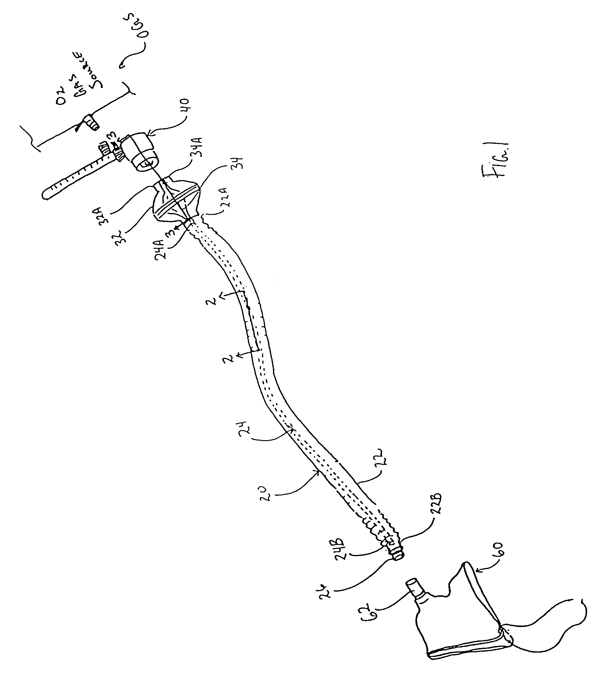
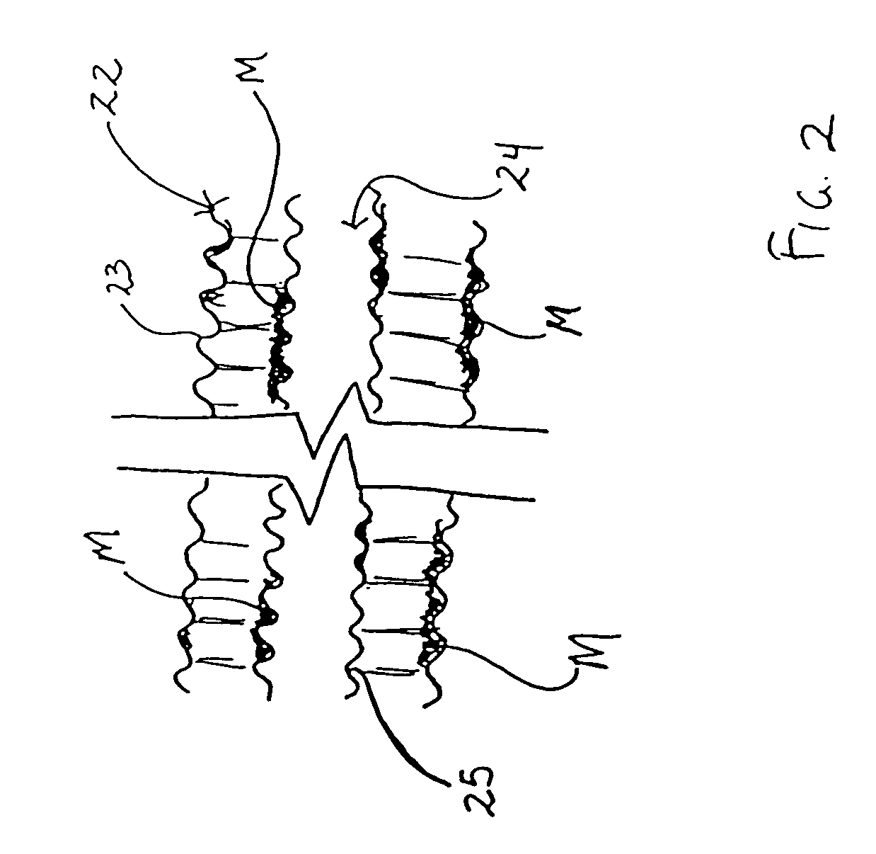
[0046]Referring now to FIGS. 1–2, the present invention in a preferred embodiment is an apparatus 10, and associated method, for humidification of inspired gases, wherein apparatus 10 preferably generally comprises unilimb breathing circuit 20, reverse flow adapter 40 and face tent 60.

[0047]Specifically, unilimb breathing circuit 20 is preferably comparable to those disclosed in U.S. Pat. No. 4,265,235 to Fukunaga, U.S. Pat. No. 5,404,873 to Leagre et al., and U.S. Pat. No. 6,439,231 to Fukunaga et al. and, as such, is preferably utilized to administer anesthe...


PUM


Abstract

An apparatus and method for humidification of inspired gases, wherein the present invention utilizes moisture from condensed expiratory gases deposited within the outer expiratory tube of a conventional unilimb breathing circuit to humidify oxygen gas (or any other inspiratory gas) for subsequent patient inhalation, and wherein the oxygen gas may be directed through the outer expiratory tube via a novel reverse flow adapter coupled to an oxygen gas source. The present invention preferably functions to effectively eliminate prior art methods of oxygen gas humidification that depend upon the wasteful utilization of bottles of sterile water, corrugated tubing, nebulizer adapters and excess consumption of oxygen gas; thus, effectuating a cost savings for the patient and contributing to overall environmental conservation efforts.

Description

CROSS-REFERENCE AND PRIORITY CLAIM TO RELATED APPLICATIONS[0001]To the fullest extent permitted by law, the present continuation-in-part application claims priority to and the full benefit of nonprovisional patent application entitled “Apparatus and Method For Humidification of Inspired Gases”, filed on May 13, 2003, having assigned Ser. No. 10 / 436,535.TECHNICAL FIELD[0002]The present invention relates generally to artificial ventilation systems, and more specifically to an apparatus and method for humidification of inspired gases, wherein the present invention is particularly suitable for, although not strictly limited to, the administration of humidified oxygen gas to patients recovering in a post-anesthesia care unit of a medical facility.BACKGROUND OF THE INVENTION[0003]Breathing circuits are commonly utilized in the operating room of a medical facility to convey anesthesia or inspiratory gases from an anesthesia machine to a patient, and to route expiratory gases from the patie...

Claims


Application Information

Patent Timeline
Patent Type & Authority Patents(United States)
IPC IPC(8): A61M15/00A61M15/08A61M16/00A62B9/02A61M16/06A61M16/08A61M16/10
CPCA61M16/08A61M16/1045A61M16/1095A61M16/0677A61M16/1065A61M16/107A61M16/1055A61M2202/0208
Inventor DAUGHERTY, ROGERWILSON, DERRICK
Owner DAUGHERTY ROGER
Why Eureka
Try Eureka