Resonant microcavity display utilizing mirrors exhibiting anomalous phase dispersion

Inactive Publication Date: 2006-03-07
QUANTUM VISION
View PDF6 Cites 37 Cited by
  • Summary
  • Abstract
  • Description
  • Claims
  • Application Information

AI Technical Summary

Benefits of technology

[0006]The subject invention is a resonant microcavity display utilizing mirrors which exhibit anomalous phase dispersion. It is the purpose of this invention to increase the amount of useable light generated by optimizing the internal net phase of the microca

Problems solved by technology

The amount of light emitted in directions other than perpendicular to the active layer and at other frequencies ot

Method used


Image

  • Resonant microcavity display utilizing mirrors exhibiting anomalous phase dispersion
  • Resonant microcavity display utilizing mirrors exhibiting anomalous phase dispersion
  • Resonant microcavity display utilizing mirrors exhibiting anomalous phase dispersion

Examples


Embodiment Construction

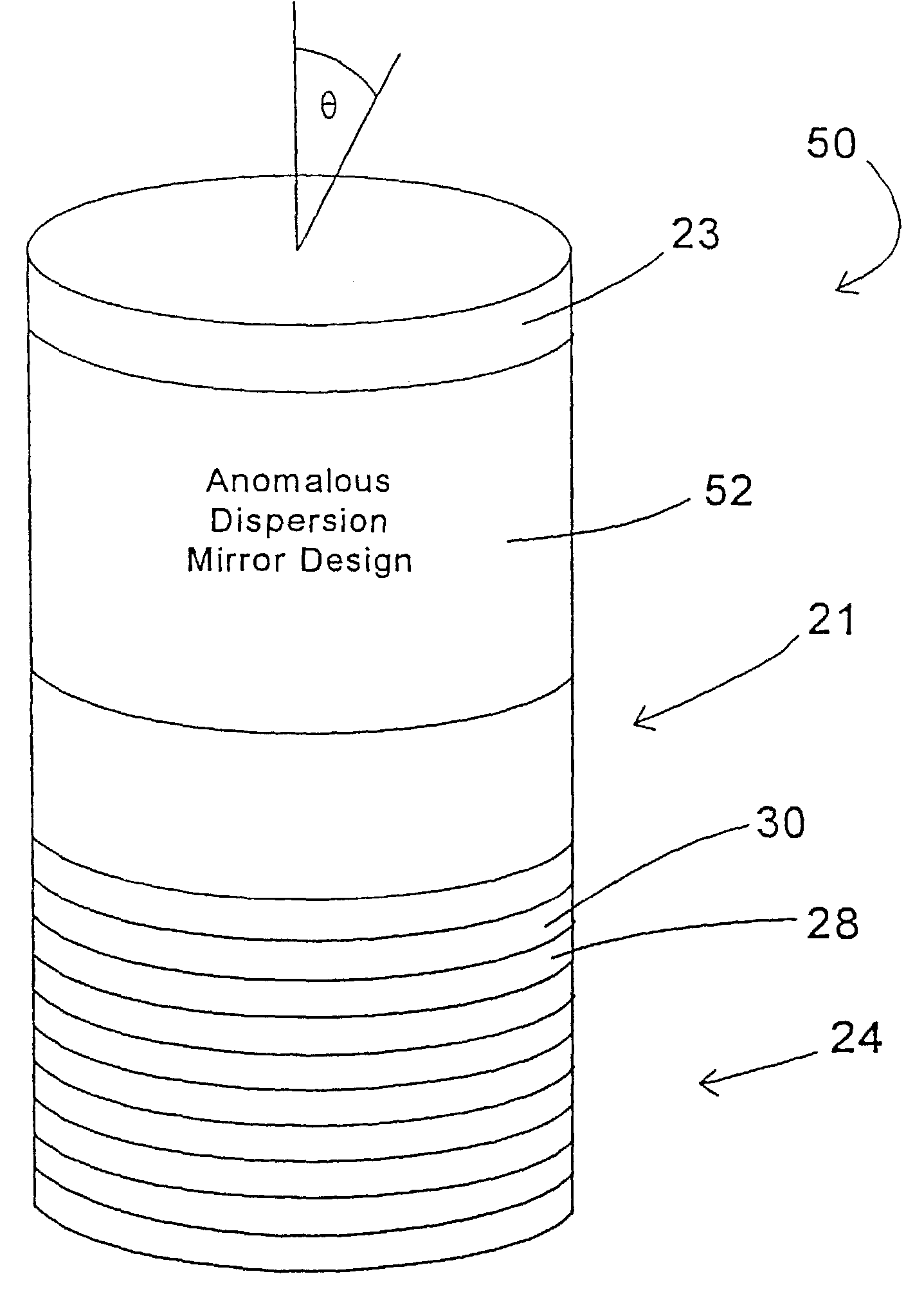
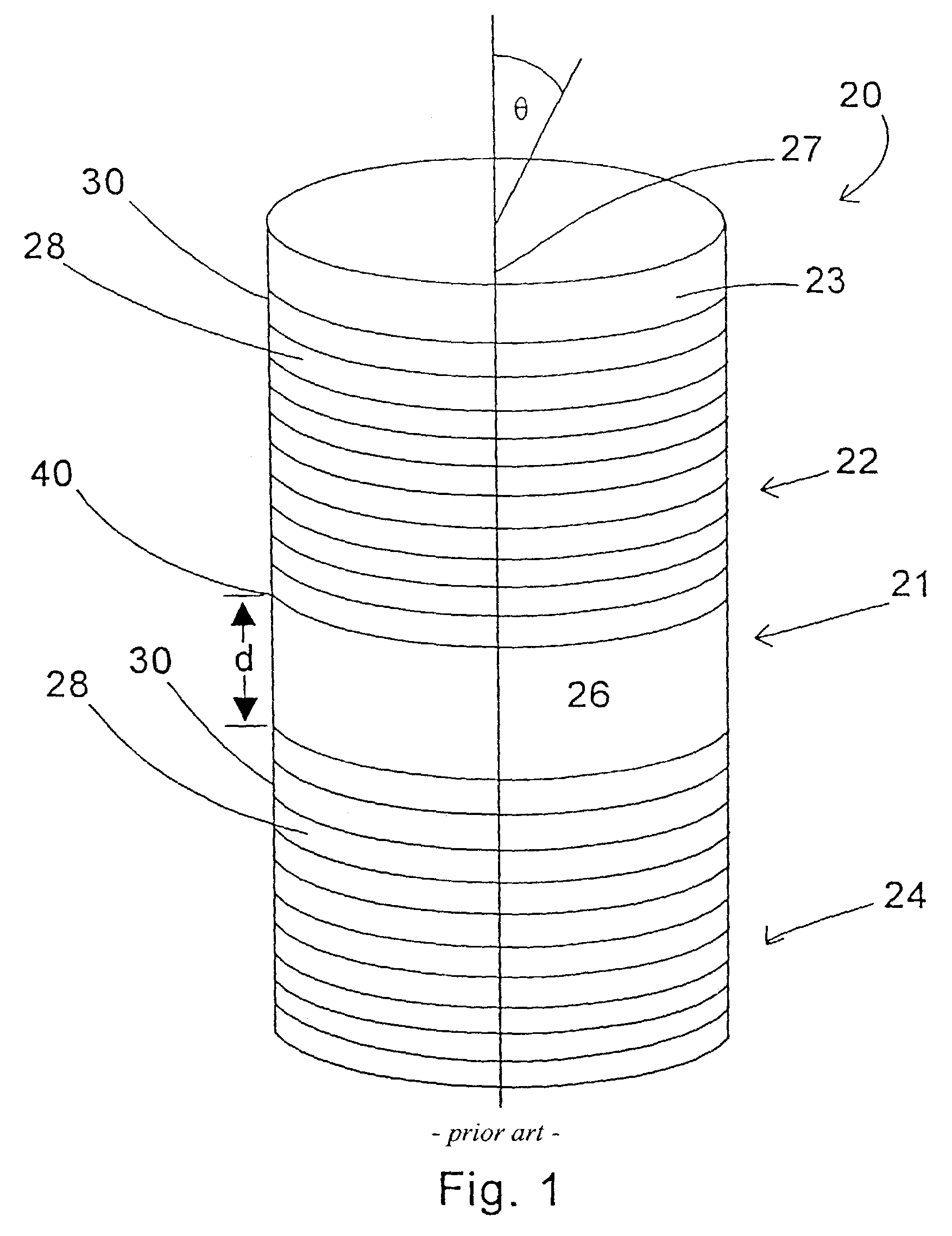
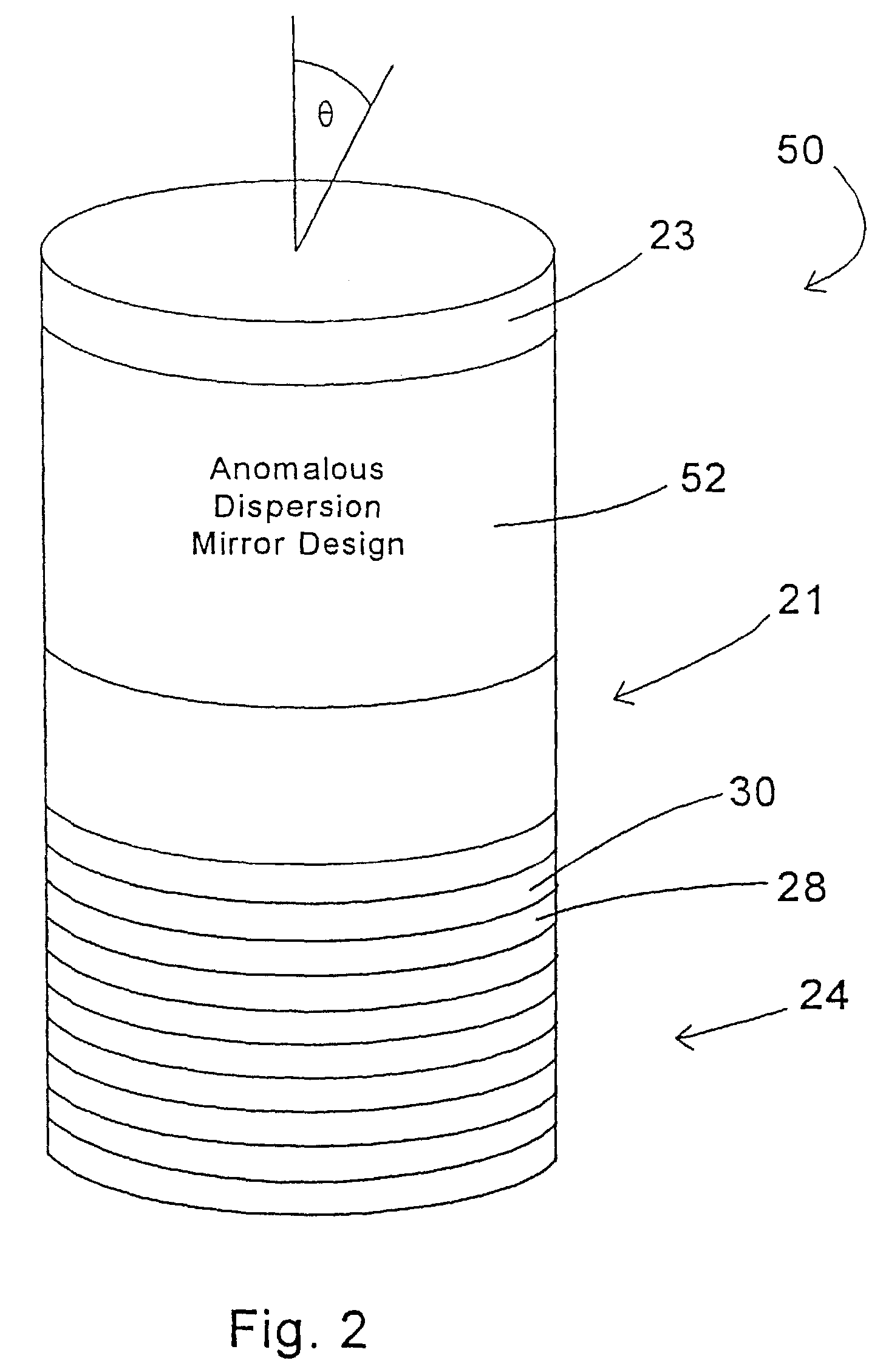
[0012]FIG. 1 illustrates a resonant microcavity 20, with an active region 21 preferably containing a phosphor, and front and back mirrors 22, 24, and grown on a substrate 23. For discussion purposes the phosphor is assumed to be transparent and isotropic since this corresponds to the majority of phosphors. While this embodiment has an active region containing an isotropic, transparent phosphor, other embodiments can have active regions of different designs. By way of example, the active regions could be comprised of anisotropic phosphors, semiconductor devices, quantum wells, organic materials, and / or other inorganic materials.

[0013]The spontaneously emitted light from the phosphor in the active region 21 can be described by the use of cavity quantum electrodynamic (QED) theory. To first order, cavity QED predicts that the spontaneous emission into a certain optical mode is proportional to the intensity of that mode at the location of the emitter. This effect is described by Fermi's...


PUM


Abstract

A resonant microcavity display comprises a thin-film resonant microcavity (20, 50, 60) with an active layer (21). The microcavity (20, 50, 60) comprises a front reflector (22, 52), the active region (21) deposited upon the front reflector, and a back reflector (20, 54) deposited upon the active region (21). The display preferentially emits light that propagates along the axis (27) perpendicular to the plane of the display, due to its quantum mechanical properties. The extrinsic efficiency of this device is increased by the use of thin film construction with anomalous phase dispersion.

Description

CROSS-REFERENCE TO RELATED APPLICATIONS[0001]This application is a continuation of Ser. No. 09 / 695,630 filed Oct. 24, 2000 now U.S. Pat. No. 6,649,432, which claims priority to Ser. No. 60 / 161,248, filed Oct. 25, 1999 which are incorporated herein by reference.FIELD OF THE INVENTION[0002]The present invention relates to a luminescent device comprising a resonant microcavity having an active region.BACKGROUND OF THE INVENTION[0003]In issued U.S. Pat. No. 5,469,018, which is incorporated herein by reference along with PCT Application PCT / US94 / 08306(International Publication No. WO 95 / 03621), a resonant microcavity display and method of making same are disclosed. A resonant microcavity display is a luminescent display incorporating a thin-film phosphor embedded in a resonant microcavity. The microcavity resonator consists typically of an active region comprising a phosphor sandwiched between two reflectors or mirrors.[0004]A display is further formed by coupling an excitation source to...

Claims


Application Information

Patent Timeline
IPC IPC(8): H01L29/22H01L33/46H01L51/52
CPCH01L33/465H01L51/5265H10K50/852
Inventor EILERS, HERGENJAFFE, STEVEN M.OLMSTED, BRIAN L.JONES, MICHIEAL L.
Owner QUANTUM VISION
Why Eureka
Try Eureka