Vehicle mounted satellite tracking system

a satellite tracking and vehicle mount technology, applied in direction finders, instruments, antennas, etc., can solve the problem of low probability of reception loss, and achieve the effect of enhancing user experien

Inactive Publication Date: 2006-03-07
VALUE STREET CONSULTING GRP
View PDF7 Cites 39 Cited by
  • Summary
  • Abstract
  • Description
  • Claims
  • Application Information

AI Technical Summary

Benefits of technology

[0015]An advantage of the present invention is that the use of low profile antennas with high gains and narrow beams is enabled, thus enhancing the user experience.
[0016]Another advantage is that the satellite tracking system overcomes the limitations of prior art systems by using a more accurate vehicle attitude track

Problems solved by technology

The signal from the satellite can be quickly acqui

Method used


Image

  • Vehicle mounted satellite tracking system
  • Vehicle mounted satellite tracking system
  • Vehicle mounted satellite tracking system

Examples


Embodiment Construction

[0027]The embodiments discussed below are not intended to be exhaustive or limit the invention to the precise forms disclosed in the following detailed description. Rather, the embodiments are chosen and described so that others skilled in the art may utilize their teachings.

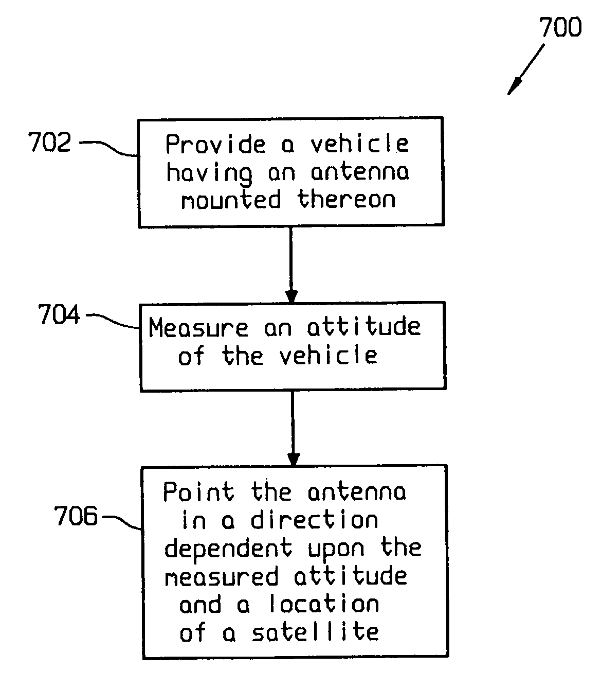
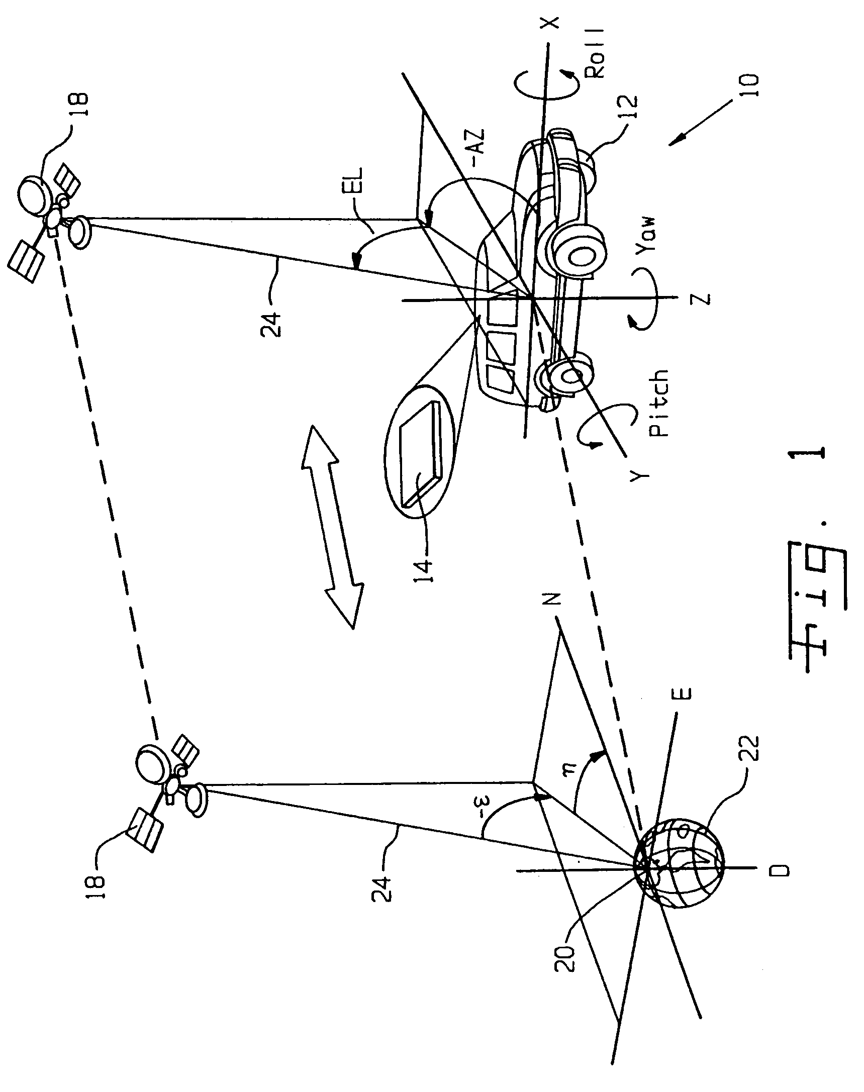
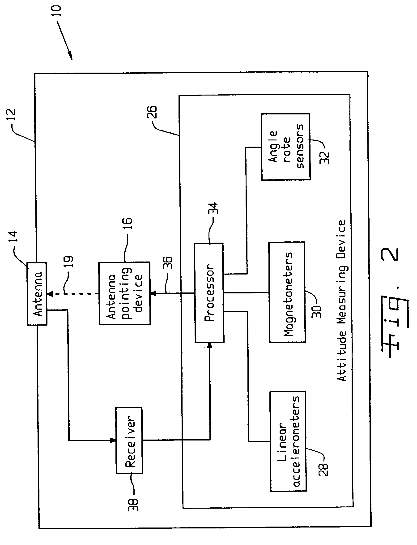
[0028]Referring now to the drawings, and particularly to FIG. 1, there is shown one embodiment of a vehicle mounted satellite tracking system 10 of the present invention including a motor vehicle 12 having an antenna 14 mounted thereon. Antenna 14 may be a flat antenna and may include a waveguide. Vehicle 12 includes an antenna pointing device 16 (FIG. 2) for pointing antenna 14 in a desired direction, such as at a satellite 18 to thereby improve the reception by antenna 14 of a signal transmitted by satellite 18. The control of the pointing direction of antenna 14 by antenna pointing device 16 is indicated by dashed arrow 19. Antenna pointing device 16 may control the direction in which antenna 14 points electr...


PUM


Abstract

A satellite tracking system includes a vehicle having an attitude measuring device for measuring an attitude of the vehicle. An antenna is mounted on the vehicle. An antenna pointing device is coupled to the antenna and points the antenna in a direction dependent upon the attitude measured by the attitude measuring device and a location of a satellite.

Description

TECHNICAL BACKGROUND[0001]The present invention relates to satellite tracking systems, and, more particularly, to mobile satellite tracking systems for use in a motor vehicle.BACKGROUND OF THE INVENTION[0002]Various methods have been employed to allow an antenna mounted on a vehicle to track a satellite with various goals and constraints. Generally utilized is a hybrid tracking system including a vehicle attitude measuring component and a satellite pointing error feedback component. More weight is typically given to the satellite pointing error feedback than to the vehicle attitude measurements.[0003]The vehicle attitude measurement component in the tracking system is usually in the form of an inertial measurement unit (IMU). The IMU may include one or more angular rate sensors and one or more linear accelerometers. The suite of sensors is usually kept to a minimum, with two accelerometers for tilt and two angular rate sensors for yaw and pitch. However, to reduce cost, sometimes on...

Claims


Application Information

Patent Timeline
IPC IPC(8): H01Q3/00
CPCG01S19/47H01Q3/08H01Q1/1257H01Q1/3275G01S19/53G01S3/44
Inventor FALL, TERRENCE L.HULES, FRANK J.
Owner VALUE STREET CONSULTING GRP
Why Eureka
Try Eureka