
Holographic printer

a holographic printer and printer technology, applied in the field of holographic printers, can solve the problems of loss of hologram image depth, redundant and wacky apertures of the prior art, and achieve the effects of better objective limiting resolution, better objective field of view, and better performan

Inactive Publication Date: 2006-03-07
XYZ IMAGING
View PDF33 Cites 49 Cited by
  • Summary
  • Abstract
  • Description
  • Claims
  • Application Information

AI Technical Summary

Benefits of technology

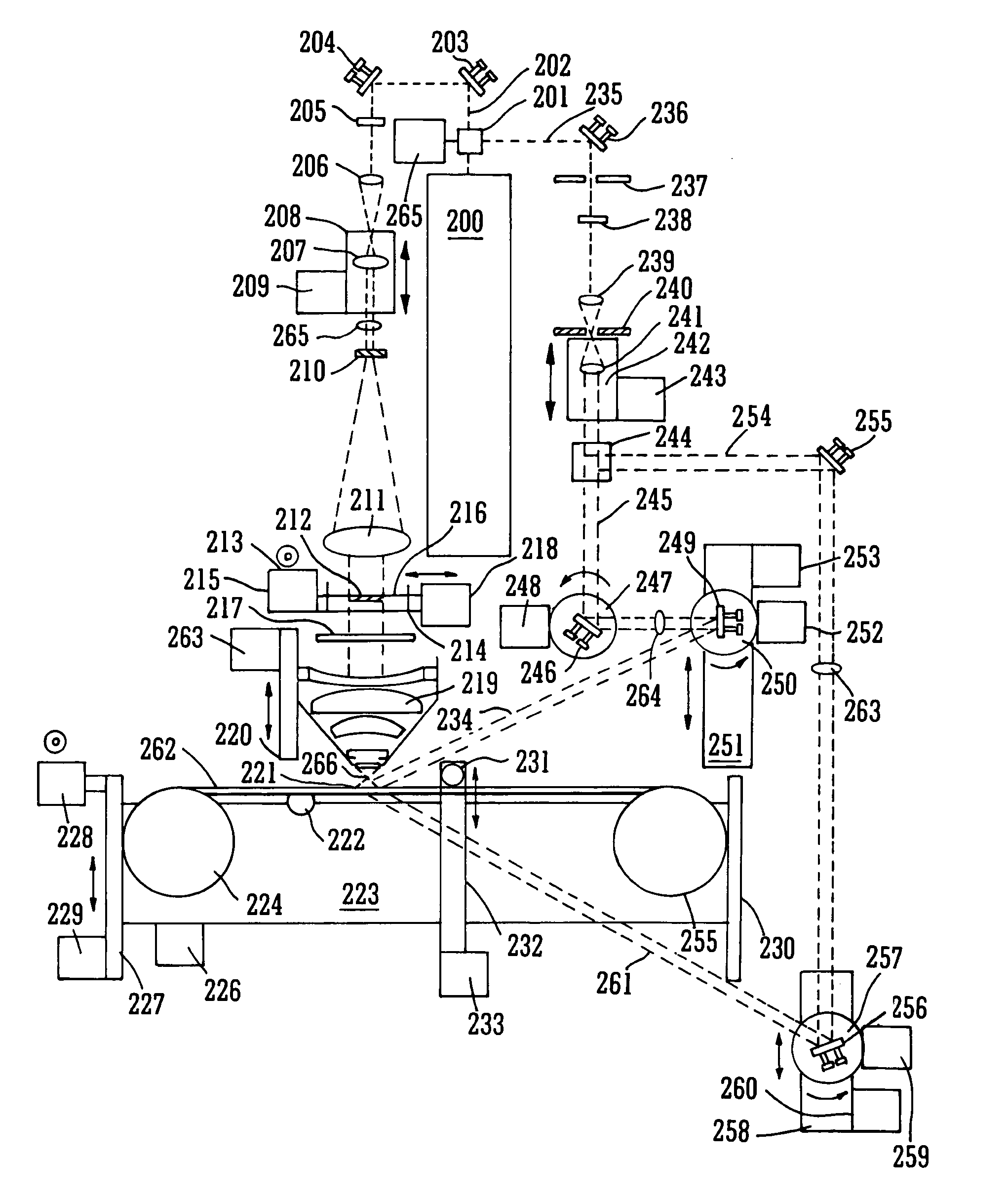
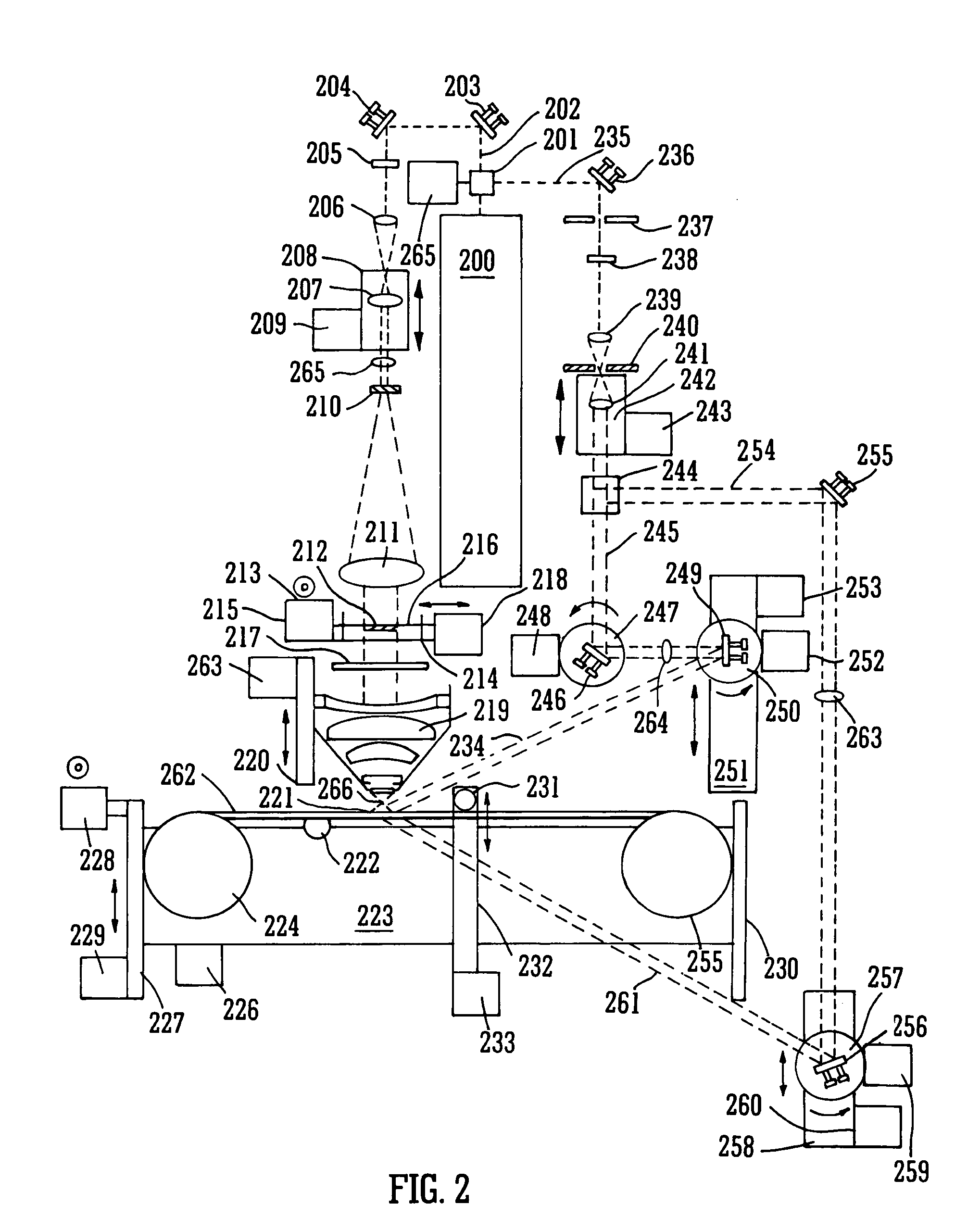
[0043]The step of using a pulsed laser as the laser source of a holographic printer is particularly advantageous since it enables the printer to operate without sensitivity to external or internal vibration or slight temperature fluctuations. In addition the speed of printing is fundamentally increased as there is no need to wait for vibration to dissipate before making an exposure. Thus the write speed is essentially determined by the refresh rate of the SLM used. Accordingly the preferred embodiment can work several orders of magnitude faster than conventional printers which use a CW laser and with a reliability of operation fundamentally higher.
[0215]Thus the preferred arrangement has many advantages over known arrangements including an energy requirement orders of magnitude lower than the prior art, dramatically increased system flexibility, lower noise results, higher speed operation and fundamentally smaller printer size.

Problems solved by technology

Fourthly, by directly exposing the photosensitive material the awkward apertures of the prior art are rendered redundant.
However, if the beam diameter at the Fourier plane becomes too large, hologram image depth will be lost.

Method used


Image

  • Holographic printer
  • Holographic printer
  • Holographic printer

Examples


Embodiment Construction

5.1 Fundamental Image Data Required

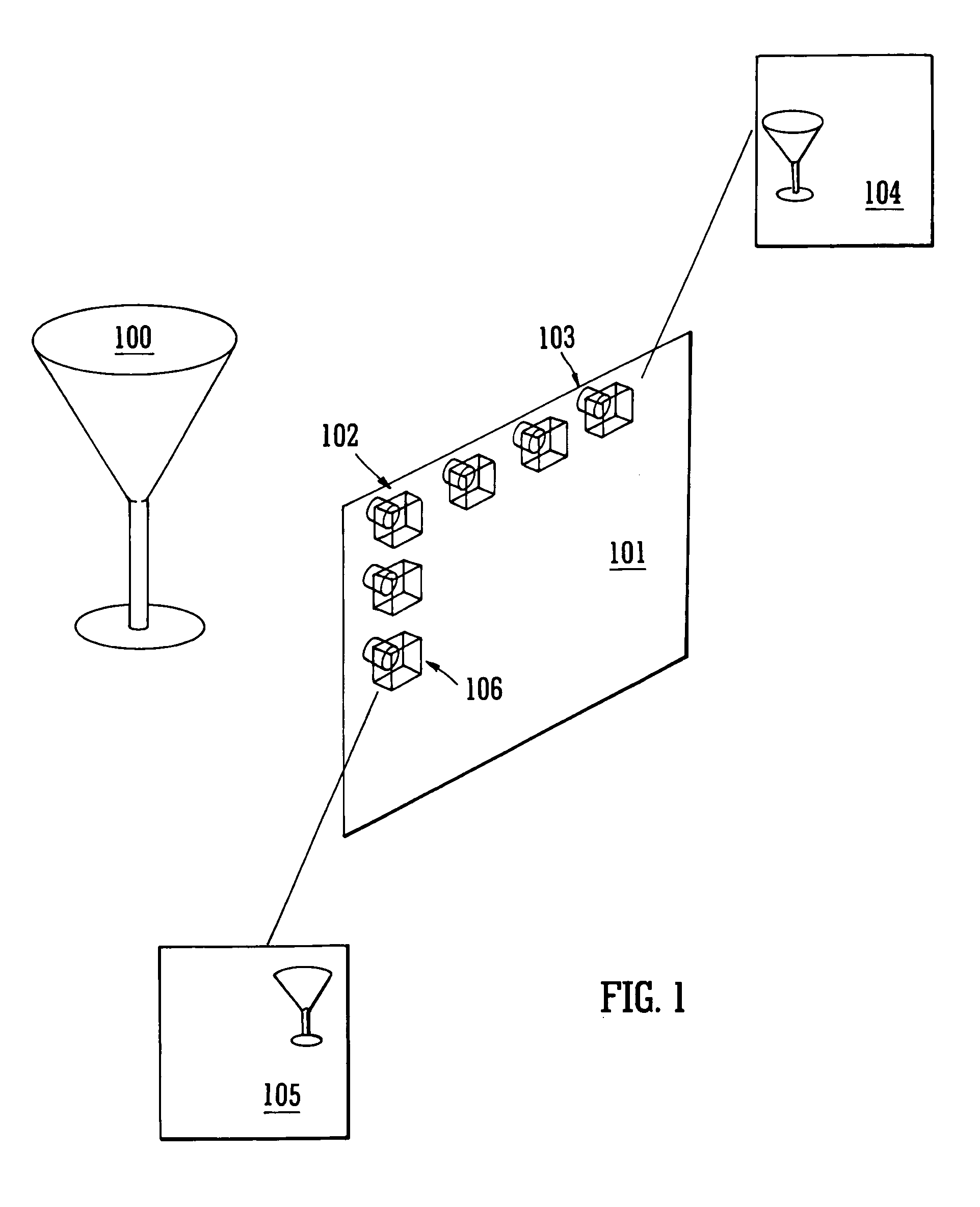
[0236]In one embodiment of this invention a computer is used to generate a three dimensional model of an object using a standard commercial computer program. Such computer programs can nowadays produce very lifelike models using a variety of sophisticated rendering processes that mimic real life effects. In addition advances in computer technology have now seen the calculation times, required for such programs to run, dramatically decreased. Three dimensional scanners using Moire or other principles now permit the incorporation of real world 3-D images in such computer models. The storage memory required for such 3-D models is largely dependent on the texture maps used therein and hence computer files representing such 3-D models are usually relatively small and may be transmitted over the internet easily. In the preferred embodiment of this invention said 3-D computer models are used to generate a series of 2-D camera views from a virtual viewing ...


PUM


Abstract

The present invention provides a single method and apparatus for producing many of the most common types of hologram from digital data is disclosed. The data are generated entirely by a computer as a 3-D (animated) model or from multiple 2-D camera images taken of a real 3-D (moving) object or scene from a plurality of different camera positions. The data are digitally processed and displayed on a small high resolution spatial light modulator (SLM). A compact low energy pulsed laser, is used to record composite holograms. The present invention permits the creation ofrestricted or full parallax master transmission or reflection type composite holograms, known as H1 holograms, that can be copied using traditional methods. Alternatively the same invention and apparatus permits the direct writing of hologram without the need to pass through the intermediate stage of the H1 transmission hologram.

Description

CROSS REFERENCES TO RELATED APPLICATIONS[0001]This application is a continuation of the U.S. Patent Application having the Ser. No. 10 / 149,211 filed Sep. 30, 2002 which is a 371 of PCT / GB00 / 04699 filed Dec. 8, 2000.BACKGROUND OF THE INVENTION[0002]The present invention relates to holographic printers. According to a preferred embodiment a method and apparatus for recording and printing holographic stereograms from digital data is disclosed.[0003]For over 50 years holograms have been produced by the general technique of illuminating an object with coherent light and arranging that the scattered light falls onto a photosensitive recording material that is also illuminated by a mutually coherent reference beam (see for instance E. N. Leith et al., “Reconstructed Wavefronts and Communication Theory”, Journal of the Optical Society of America 53, 1377–81 1963). However, with such a technique one requires a physical object in order to make an holographic representation of this object and ...

Claims


Application Information

Patent Timeline
Patent Type & Authority Patents(United States)
IPC IPC(8): G03H1/26B41J2/44G02B13/00G02B13/22G03H1/12G03H1/16G03H1/24
CPCG03H1/24G03H1/268G03H1/0891G03H2210/441G03H2001/0216G03H2001/0413G03H2001/0415G03H2001/0428G03H2001/0473G03H2001/2263G03H2001/2265G03H2001/2268G03H2001/2273G03H2001/2685G03H2001/269G03H2001/2695G03H2001/306G03H2210/22G03H2210/40G03H2210/42G03H2210/454G03H2222/22G03H2222/33G03H2222/50G03H2223/19G03H1/16G03H2001/043
Inventor BROTHERTON-RATCLIFFE, DAVIDVERGNES, FLORIAN MICHEL ROBERTRODIN, ALEXEYGRICHINE, MIKHAIL
Owner XYZ IMAGING
Learn More