
Moving image coding apparatus and decoding apparatus

a coding apparatus and moving image technology, applied in the field of moving image coding apparatus and moving image decoding apparatus, can solve the problems of large degradation of the decoded video signal, the inability to decode not only the lost rtp packet, but also the video bit stream, and the inability to decode the decoded moving image signal. , to achieve the effect of simplifying the processing of entering header information and suppressing the adverse effect of the loss of the rtp pack

Inactive Publication Date: 2006-03-07
KK TOSHIBA
View PDF5 Cites 77 Cited by
  • Summary
  • Abstract
  • Description
  • Claims
  • Application Information

AI Technical Summary

Benefits of technology

[0016]The invention has been made to solve the above problem, and therefore an object of the invention is to provide a moving image coding apparatus and a moving image decoding apparatus for suppressing the adverse effect of an RTP packet loss when a moving image signal is coded and is transmitted using an RTP packet and simplifying processing of entering header information in an RTP header.

Problems solved by technology

Thus, if a transmission line error such as a packet loss occurs on a transmission line or medium for transmitting an RTP packet, it is made impossible to decode not only the lost RTP packet, but also the video bit stream in any other RTP packet to be decoded using the header information of the video bit stream contained in the lost RTP packet.
Consequently, the transmission line error causes large degradation to occur in the decoded video signal; this is a problem.
However, the extended RTP format involves the following problems:(1) To prepare and transmit an RTP packet in a coding apparatus, processing of entering the header information contained in a video code string in an RTP packet header must be performed.
As described above, to transmit packets undergoing system multiplexing in RTP packets in the coding apparatus for coding a moving image signal and transmitting the coded signal using an RTP packet, when the RTP packet containing important information such as the header information on a video bit stream is lost, this error also affects other RTP packets, causing large degradation to occur in the decoded moving image signal.
To use the RTP format proper to video coding, processing for entering the header information contained in a video code string in an RTP header becomes intricate.

Method used


Image

  • Moving image coding apparatus and decoding apparatus
  • Moving image coding apparatus and decoding apparatus
  • Moving image coding apparatus and decoding apparatus

Examples


first embodiment

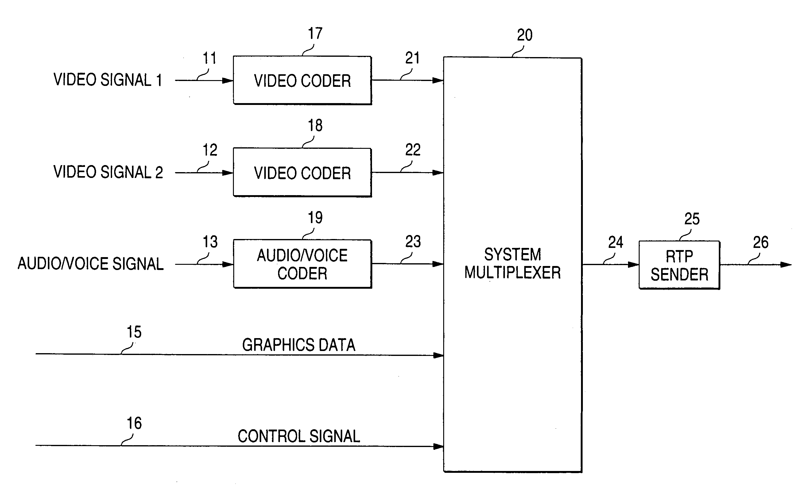
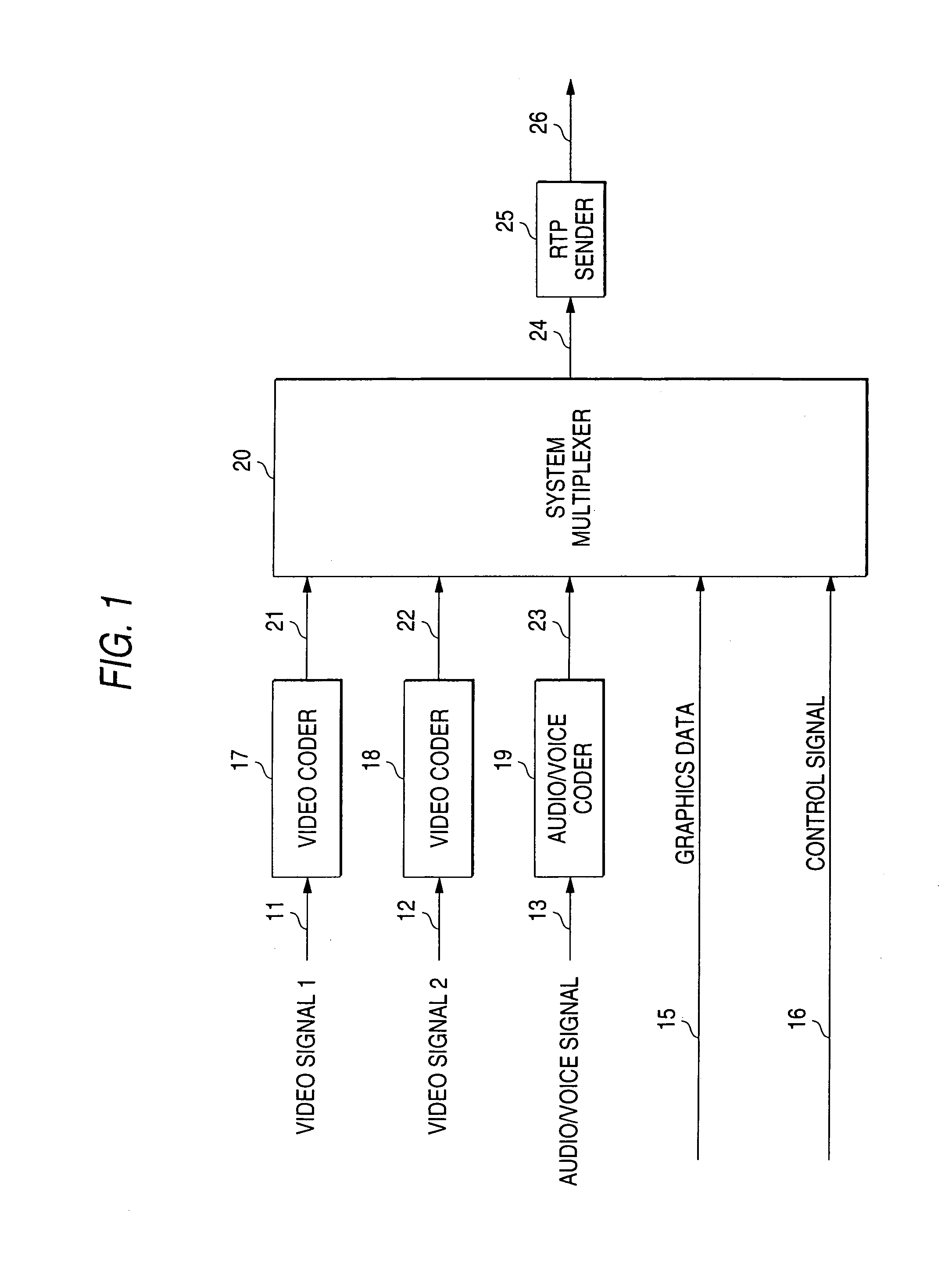
[0042]FIG. 1 shows the configuration of a coding apparatus according to a first embodiment of the invention. Video signals 11 and 12 and an audio / voice signal 13 input from input means for inputting a moving image, such as a camera or a videocassette recorder (VCR), and converted into digital signals are input to video coders 17 and 18 and an audio / voice coder 19 respectively. Graphics data 15 and a control signal 16 for performing control are input to a system multiplexer 20.

[0043]The video signals 11 and 12 are compressed and coded by the first and second video coders 17 and 18 and are input to the system multiplexer 20 as first and second video code strings 21 and 22. The audio / voice signal 13 is compressed and coded by the audio / voice coder 19 and is input to the system multiplexer 20 as an audio / voice code string 23.

[0044]The video code strings 21 and 22, the audio / voice code string 23, the graphics data 15, and the control signal 16 are multiplexed by the system multiplexer 20...

second embodiment

[0075]FIG. 9 shows the configuration of a coding apparatus according to a second embodiment of the invention. Parts identical with those previously described with reference to FIG. 1 are denoted by the same reference numerals in FIG. 9 and only the differences from the coding apparatus of the first embodiment will be discussed. The coding apparatus of the second embodiment differs from that of the first embodiment in that it does not include the system multiplexer in the first embodiment, that first and second code strings 21 and 22, an audio / voice code string 23, graphics data 15, and a control signal 16 are input to RTP senders 151, 152, 153, 154, 155, and 156, and that RTP packets 161, 162, 163, 164, 165, and 166 are also output separately. The RTP packets are multiplexed on an IP packet layer (not shown).

[0076]FIG. 10 shows an example of an RTP packet corresponding to a video code string. The RTP header fields are given the same names as the information pieces contained in the R...

third embodiment

[0099]FIG. 13 shows the configuration of a coding apparatus according to a third embodiment of the invention. Parts identical with those previously described with reference to FIGS. 1 and 9 are denoted by the same reference numerals in FIG. 13 and only the differences will be discussed in detail.

[0100]First, control information 16 is input to a control information sender 1056. The control information 16 contains information indicating the coding system and mode applied when a video coder 17 compresses and codes a video signal 11, information indicating the coding system and mode applied when an audio / voice coder 19 compresses an audio / voice signal 13, and information indicating the RTP coding system and mode applied in RTP senders 151 and 153.

[0101]The information indicating the coding system and mode may include the following:[0102]Video coding method (MPEG-1, MPEG-2, MPEG-4, H.261, H.263, JPEG, etc.,), profile level (main profile main level, simple profile level 1, etc.,), coding ...


PUM


Abstract

A moving image coding apparatus which has coders (17, 18, 19) for dividing an input moving image signal into a plurality of frames, dividing each of the frames into one or more image areas, compressing and coding the image areas, and outputting an area image code string, a system multiplexer (20) for separating frame header information indicating the coding mode, etc., of the frame frame from the frame frame and adding the frame header information to one or more coded area image code strings, and a sender (25) for collecting one or more area image code strings to which the frame header information is added, adding packet header information, putting into a packet, and sending the packet.

Description

DETAILED DESCRIPTION OF THE INVENTION[0001]1. Field of the Invention[0002]This invention relates to a moving image coding apparatus and a moving image decoding apparatus used with a system for compressing, coding, and multiplexing an image and voice and transmitting them via a network and particularly used with a system for transmitting a compressed image and voice on a packet-based network such as an intranet or the Internet.[0003]2. Description of the Related Art[0004]In video telephones, videoconference systems, digital television broadcasting, etc., a technique for compressing and coding a moving image and voice to less information amounts, multiplexing compressed moving image code string, voice code string, and data code string into one code string, and transmitting and storing the code string is used.[0005]Techniques of motion compensation, discrete cosine transform (DCT), sub-band coding, pyramid coding, variable-length coding, etc., and systems provided by combining the tech...

Claims


Application Information

Patent Timeline
IPC IPC(8): H04N7/12G06T9/00H04N7/24
CPCG06T9/007H04N21/234318H04N21/2368H04N21/8547H04N21/4307H04N21/6437H04N21/2381H04N21/43072
Inventor KIKUCHI, YOSHIHIROMASUDA, TADAAKINAGAI, TAKESHI
Owner KK TOSHIBA
Learn More