Filling valve

Active Publication Date: 2006-03-14
PROMACH FILLING SYST LLC
View PDF4 Cites 31 Cited by
  • Summary
  • Abstract
  • Description
  • Claims
  • Application Information

AI Technical Summary

Benefits of technology

[0013]The improved filling valve of the present invention is particularly useful in automated liquid filling systems for filling containers with liquid products. The valve of the present invention is a plunger style valve, as opposed to valves having valve seats and a seal which seals on the valve seat. Instead of a valve seal, the filling valve of the presen

Problems solved by technology

However, this may require increasing the diameter of the rotor.
These valves have various drawbacks when used for filling containers with semi-viscous liquids and/or liquids having mixed-in solid particles or particulate.
A significant drawback to each of the previously described valves is that the valves have areas prone to clogging and product entrapment.
In addition,

Method used


Image

  • Filling valve
  • Filling valve
  • Filling valve

Examples


Embodiment Construction

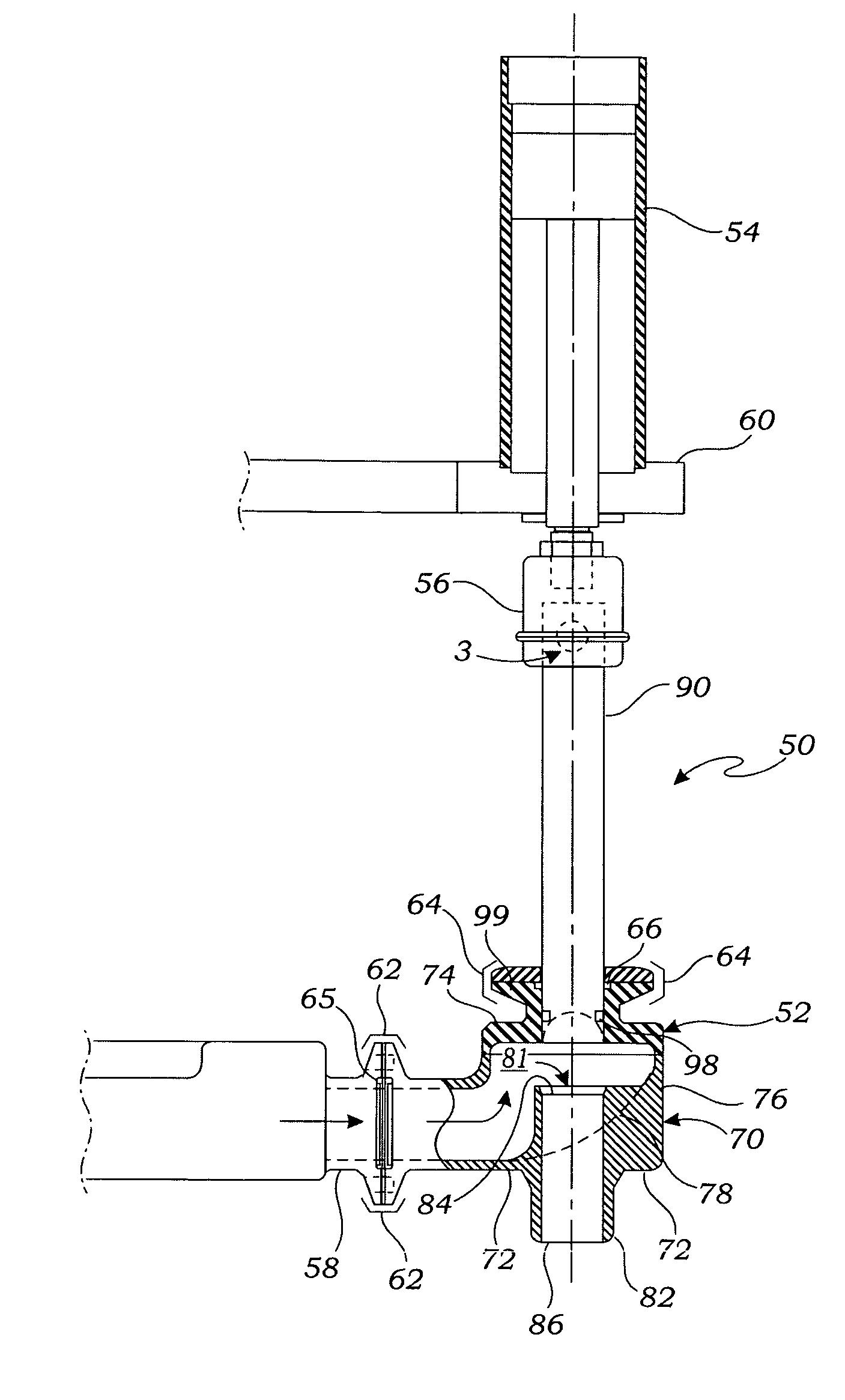
[0029]Turning to FIG. 3 and FIG. 4, a filling valve 52 according to the present invention is shown incorporated into a filling station assembly 50. The filling station assembly 50 includes the filling valve 52 operably coupled to an air cylinder actuator 54 by a coupler 56. A product supply pipe 58 is attached to a product inlet port 88 of the filling valve 52 by a clamp 62. A sanitary inlet seal 65 is provided between the supply pipe 58 and the inlet port 88 to provide a liquid tight seal. The seal 65 is preferably a clean-in-place seal such that the seal 65 and surrounding valve structure may be cleaned without disassembling the inlet port 88 from the supply pipe 58. A cap retainer 64 is attached to a cap 74 of the valve 52 by a clamp 64. A sanitary cap seal 66 is held in place by the cap retainer 64. The sanitary seal 66 helps seal the valve 52 by preventing product from flowing between the plunger 90 and the outlet tube 82 of the valve 52. The seal 66 is preferably a clean-in-pl...


PUM


Abstract

An improved filling valve and liquid filling machine comprising such valve are herein disclosed. The filling valve comprises a housing having a base, a cap and a sidewall extending between the base and the cap thereby defining a chamber. The base has a ramp which slopes from a bottom surface of the base toward the cap. An outlet tube extends from said housing and has an inlet opening in fluid communication with the chamber. An inlet port extends through the sidewall to allow liquid product to enter the chamber. A plunger guide having an opening is provided on the cap with the opening extending through the cap. A plunger is slidably received in the outlet tube and the opening in the plunger guide. The plunger is movable between a position in which the plunger seals the outlet tube thereby closing the valve and a position in which the plunger is withdrawn from the outlet tube thereby unsealing the outlet tube and thereby opening the valve. The filling valve may be utilized on a liquid filling machine to fill containers with liquid product.

Description

FIELD OF THE INVENTION[0001]The present invention relates generally to the field of liquid filling machinery for filling containers such as bottles, cans, and jars, and more particularly to an improved filling valve for use in such machinery.BACKGROUND OF THE INVENTION[0002]The high-throughput filling of containers with liquids is accomplished using precision, automated liquid filling systems. These high speed liquid filling systems are used for filling containers such as bottles, cans and jars with a wide variety of consumer products including foods, drinks, personal care products, home care products, automotive products, pharmaceuticals and more.[0003]A typical liquid filling system includes a container handling device, a liquid filling machine and a capping / lidding machine. The container handling device transports unfilled containers to the liquid filling machine and then transports the filled containers from the filling machine to the capping / lidding machine. The container handl...

Claims


Application Information

Patent Timeline
IPC IPC(8): B65B1/04
CPCB67C3/001B67C3/2608B67C3/206
Inventor CARPINO, GERALD ALBERTCARPINO, PETER TODD
Owner PROMACH FILLING SYST LLC
Why Eureka
Try Eureka