Flash welded joint structure and method for making a joint structure

a technology of flash welding and joint structure, which is applied in the direction of bumpers, roofs, manufacturing tools, etc., can solve the problems of adding considerable weight to the frame structure formed by this method, the last member to be mounted in an assembly or sub-assembly, etc., and achieves the effect of facilitating a break in the continuity of an interfa

Inactive Publication Date: 2006-03-14
ARCONIC INC
View PDF17 Cites 12 Cited by
  • Summary
  • Abstract
  • Description
  • Claims
  • Application Information

AI Technical Summary

Benefits of technology

[0012]The present invention also includes a method of forming a joint for a vehicle body-in-white comprising the steps of (1) inserting a first component having a lineal member with a pair of ends into an opening in a second component having a surface and boss extending from the surface, the opening extending through the boss, such that an end of the boss and the one end of the lineal member are coterminous; and (2) attaching a cap member onto the coterminous one end of the lineal member and the boss end. The attaching step preferably is accomplished by friction welding or flash welding. A gap may be defined between the second component boss and the lineal member, and the method may further include a step of inserting a sleeve into the gap. The sleeve may include a discontinuous ring such that a diameter of the sleeve is variable between a maximum and minimum limit. The sleeve has a first face and a second face such that when positioned between the second component boss and the first component lineal member, the second face is proximate the cap member. The sleeve discontinuous second face facilitates a break in the continuity of an interface between the sleeve second face and the cap member during the step of welding the joint.

Problems solved by technology

However, this technique has the disadvantage that the last member to be mounted in an assembly or subassembly could only be mounted by flexing or bending the structure.
In addition, because the Fussnegger et al. castings may be of considerable size, they may add considerable weight to the frame structure formed by this method.

Method used


Image

  • Flash welded joint structure and method for making a joint structure
  • Flash welded joint structure and method for making a joint structure
  • Flash welded joint structure and method for making a joint structure

Examples


Embodiment Construction

[0037]For purposes of the description hereinafter, the terms “upper”, “lower”, “right”, “left”, “vertical”, “horizontal”, “top”, “bottom”, and derivatives thereof relate to the invention as it is oriented in the drawing figures. However, it is to be understood that the invention may assume various alternative variations and step sequences, except where expressly specified to the contrary. It is also to be understood that the specific devices and processes illustrated in the attached drawings, and described in the following specification, are simply exemplary embodiments of the invention. Hence, specific dimensions and other physical characteristics related to the embodiments disclosed herein are not to be considered as limiting.

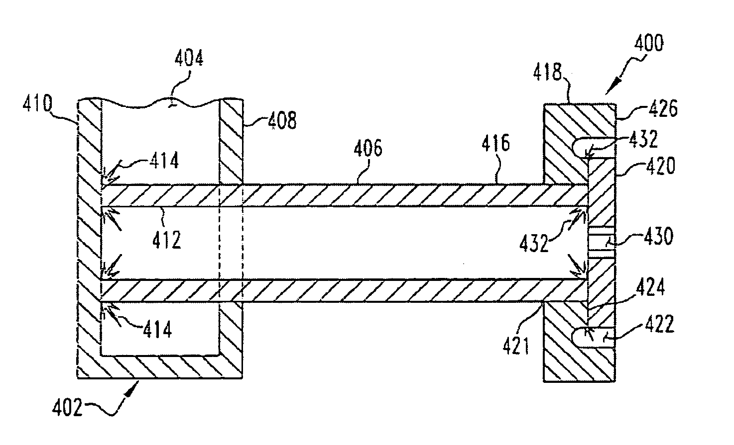
[0038]One joint structure of this invention includes the joining of concentric parts with the use of a cap member via friction welding or flash welding. Friction welding is a solid state joint process that produces coalescence of materials under compressive f...


PUM

PropertyMeasurementUnit
structureaaaaaaaaaa
diameteraaaaaaaaaa
joint structureaaaaaaaaaa

Abstract

An energy absorbing assembly for a vehicle including an elongated crash box having ends with circular cross sections. One end of the crash box is received in a bumper beam and is friction welded to an inside surface of the beam. The other end of the crash box is friction welded to a bracket assembly.

Description

RELATED APPLICATIONS[0001]This application is a continuation-in-part of U.S. application Ser. No. 10 / 108,040, filed Mar. 27, 2002, now U.S. Pat. No. 6,698,809 which is a continuation-in-part of U.S. application Ser. No. 09 / 990,807 filed Nov. 20, 2001, now U.S. Pat. No. 6,598,923, which claims the benefit of U.S. Provisional Patent Application Ser. No. 60 / 252,712 filed Nov. 22, 2000, all entitled “A Joint Structure and Method for Making a Joint Structure”.BACKGROUND OF THE INVENTION[0002]1. Field of the Invention[0003]The invention generally relates to joint structures and methods for forming joint structures that are ideally suited for use in a vehicle body-in-white. More specifically, the invention provides both a friction welded joint assembly in which lineals and sheet, cast or extruded components are joined together and a structure and method for improving the stability of the joint structure.[0004]2. Description of the Prior Art[0005]It is known that various structural componen...

Claims


Application Information

Patent Timeline
Patent Type & Authority Patents(United States)
IPC IPC(8): B60R19/26B62D23/00B62D27/02
CPCB62D23/005B62D27/023Y10T403/478Y10T29/49373
Inventor STOL, ISRAELCOBES, JOHN W.
Owner ARCONIC INC
Why Eureka
Try Eureka