Highchair helper improvements

Inactive Publication Date: 2006-03-14
RESPONSIBLE ME
View PDF95 Cites 30 Cited by
  • Summary
  • Abstract
  • Description
  • Claims
  • Application Information

AI Technical Summary

Benefits of technology

[0013]The secondary objective of this invention is to provide a detachable device that can be easily attached and removed to all tray edges on existing highchairs, booster chairs, activity chairs, strollers and car seats.
[0014]The third objective of this invention is provide an attachment device for the trays on highchairs, booster chairs, activity chairs, strollers and car seats that reduces the spillage of foods/liquids during infant feeding.
[0015]The fourth objective of this invention is to provi

Problems solved by technology

Feeding a baby can be extremely messy.
Knocked down jars of baby food can be extremely messy to clean up, as well as resulting in wasted unusable food spilled out from the jar.
For similar reasons, the baby bottles cannot be temporary stored on the existing tray since the bottles are within easy reach of the infant and can be knocked down creating additional messes and wasted liquids.
The problem comes into play when the person feeding the infant must temporarily place the bottle somewhere if they are going to start hand feeding the infant using a handheld food jar, bowl and handheld spoon.
Similar problems occur with other chairs having trays such as infant booster chairs, stroll er type chairs, stationary and movable activity chairs, and the like.
However, this temporary solution creates other problems.
In addition to taking up additional space, these surfaces need to be completely clean (bacteria and bug free) to store these objects, and generally require an extra cleanu

Method used


Image

  • Highchair helper improvements
  • Highchair helper improvements
  • Highchair helper improvements

Examples


embodiment 100

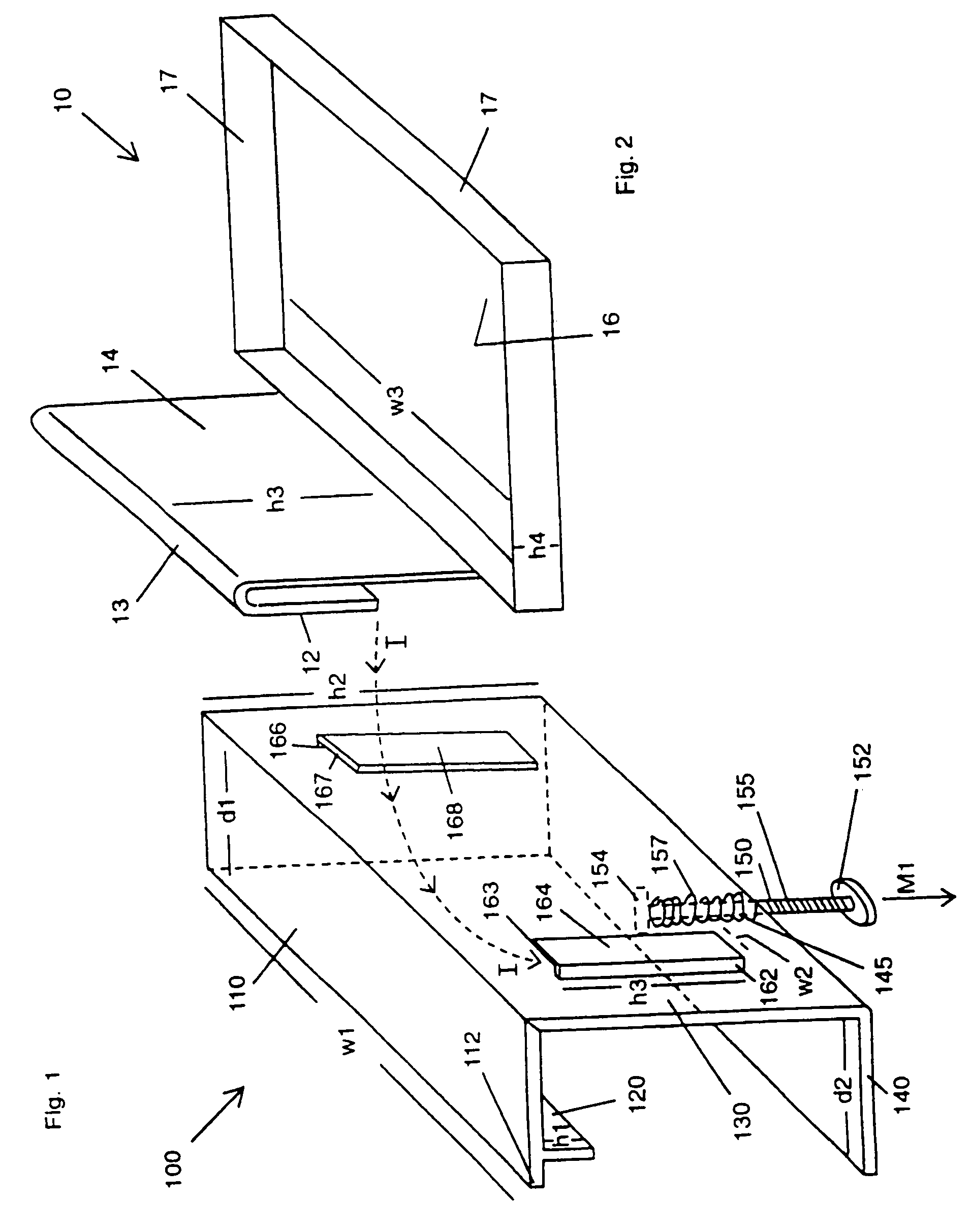
[0059]FIG. 1 is a perspective view of a first preferred embodiment 100 of the tray edge adjustable clamp of the subject invention for use with trays on highchairs, booster chairs, activity chairs and strollers. Clamp 100 includes an upper planar horizontal plate 110 having a width W1, of approximately 4 and ¼ inches, a depth d1, of approximately 1 and ½ inches. Perpendicular to plate 110 is a downwardly projecting lip 120 has a height h1, of approximately ½ an inch, which is approximately ½ inch inside of upper plate edge 112, grips about an upper raised ridge of tray which is shown in greater detail in later described drawings. Perpendicular to a rear edge of horizontal plate 110 is a vertical plate 130 having a height 112, of approximately 3 inches. On the exterior side of vertical plate 130 are dual L-shaped brackets 162,164 and 166, 168. Each bracket has vertical side portions 162, 166 having a height h3 of approximately 1 and ½ inches, with inwardly projecting clip walls 164; 1...

embodiment 200

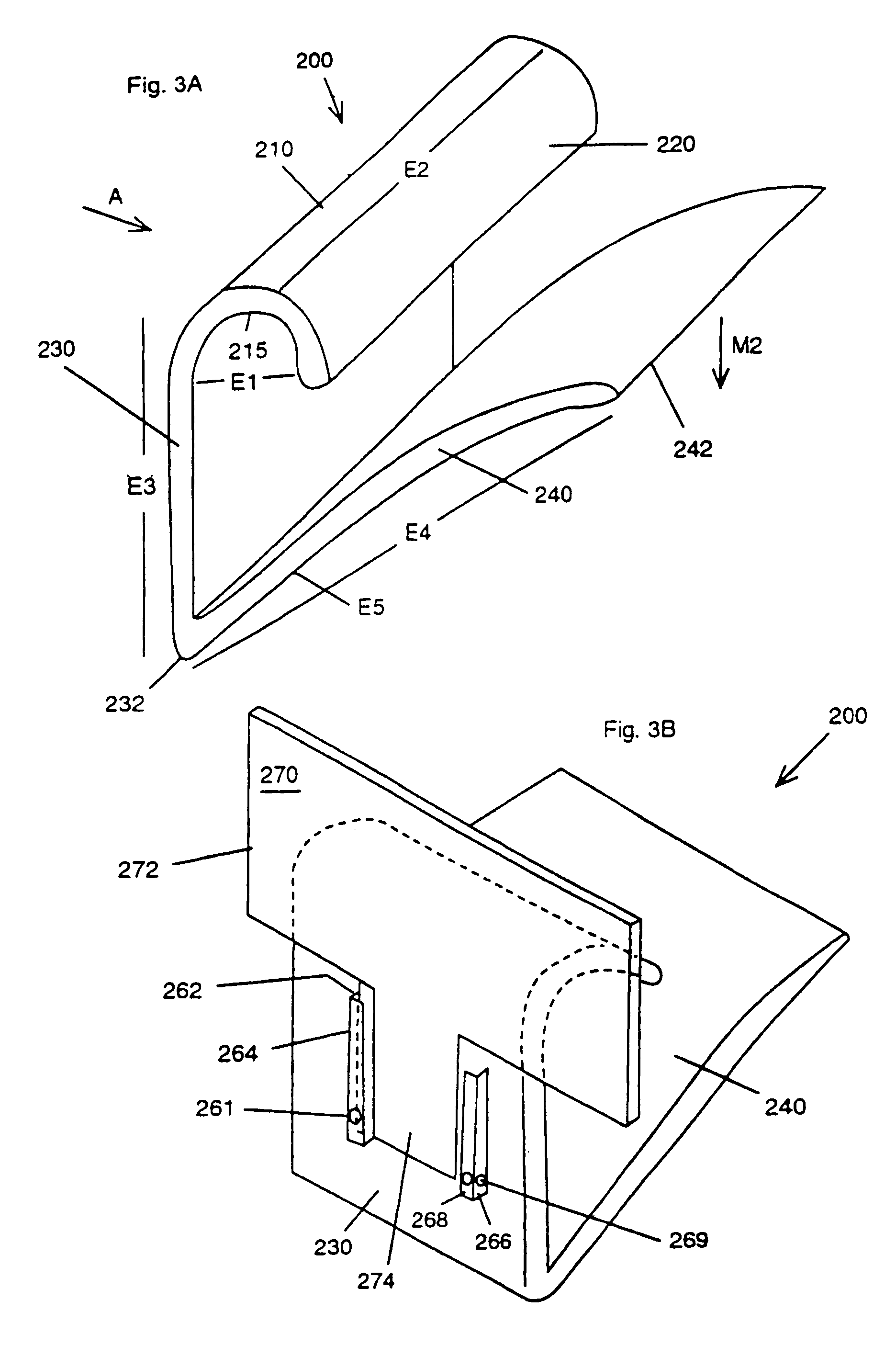
[0061]FIG. 3A is a perspective view of a second preferred embodiment 200 of the tray edge expandable clamp of the subject invention for use with trays on highchairs, booster chairs, activity chairs and strollers. Referring to FIG. 3A, expandable clamp 200 includes downwardly curved flange 210 with rounded lip tip 220 attached to a rear wall 230. The diameter E1 between lip 220 and rear wall 230 being approximately 1 inch in diameter. On the exterior side of rear wall 30 are dual clip brackets 262, 264, 268, which correspond to like components in the preceding figures. Small inwardly protruding dimples 261, 269 allow the subtray attachments to have a tighter fit to clamp 200. The width E2 of clamp 200 can be approximately 3 inches and the height E3 of rear wall 230 can be approximately 2 and ⅝ inches. connected to the lower end of rear wall 230 is an upwardly slightly concave bending flange plate 240 having an angle E5 of approximately 1 to 5 degrees, having an end 242 with a height ...

embodiment 1000

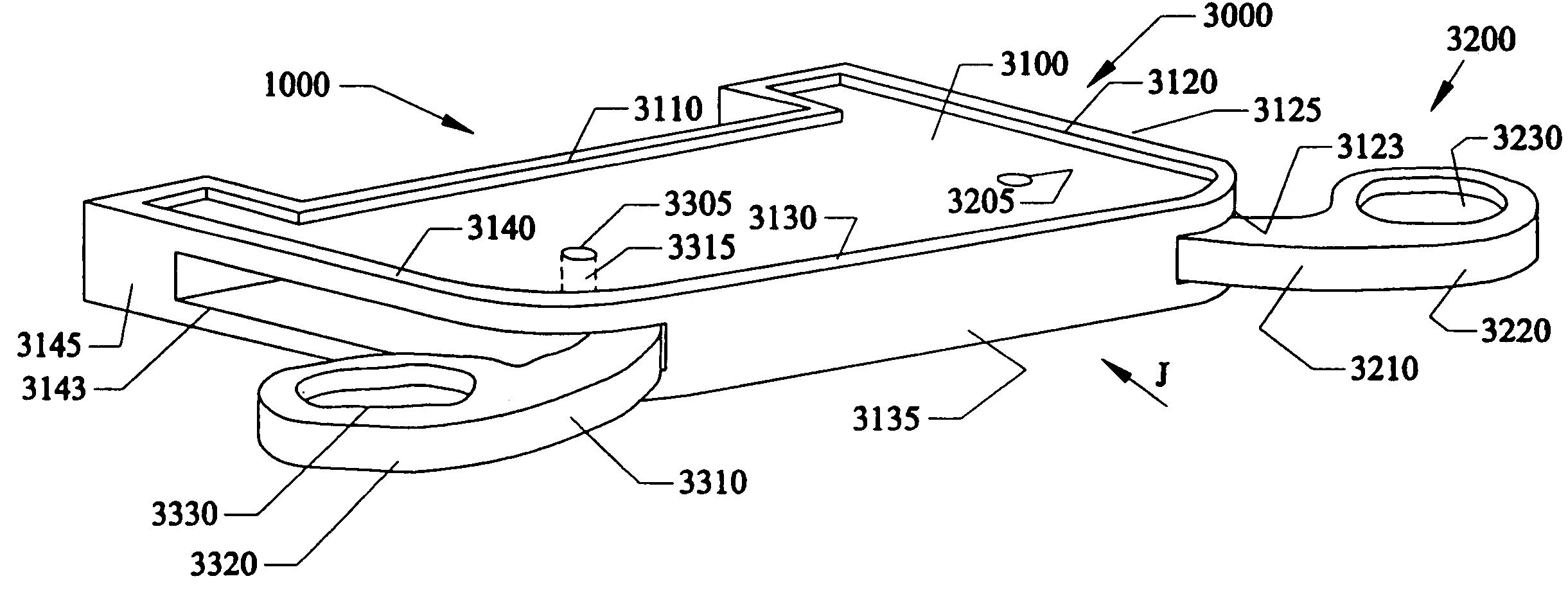
[0077]FIG. 13 is a perspective view of another embodiment 1000 of a built-on clip attachment 1140 for a main tray for a juvenile chair such as those found on highchairs, strollers, and activity chairs described above. This main tray embodiment 1000 can include a main tray surface 1100 having a rear raised perimeter edge 1110 which would be adjacent to a sitting child in a juvenile seat, side raised perimeter edges 1120 and 1125 and an outer raised perimeter edge 1130 opposite to the rear raised perimeter edge 1110. On the outer wall 1135 below the outer raised perimeter edge 1130 can be a built-on clip 1140 that can be pre-molded thereon. Here, the pre-molded clip 1140 can have a T-shape with stem portion 1142 and upper extended side arm wing portions 1144, 1146 extending from a mid-portion 1145.

[0078]FIG. 14 is a perspective view of a clipable item 1170 that can be used with the built-on clip attachment 1140 of FIG. 13. Mirror item 1170 can include a mateable second clip 1150 havin...


PUM


Abstract

Detachable bottle and food holding subtrays, clips and support attachments for juvenile chairs such as highchairs, strollers, booster chairs, car seats and activity chairs. The clips can be a snapable C-shape, use a screwable post or a spring biased post for attachment to an existing tray. Removable lids and removable bottle sizing rings can be used. Pre-attached clips can be pre-molded directly to the existing tray. Alternatively, clips can be attached by hook and loop fasteners or peel and stick tape. A drawer type subtray can slide in and out from the existing tray. Alternatively, a pivoting arm can be folded out from the existing tray. The clips, supports, drawers and arms can be used to support and/or hold items such as food out of reach of sitting children, and/or can keep items such as mirrors and toys at selected locations within reach of the sitting child.

Description

[0001]This invention is a Divisional Application of U.S. patent application Ser. No. 10 / 299,143 filed Nov. 19, 2002, which is a Continuation-In-Part of U.S. patent application Ser. No. 09 / 653,879 filed Sep. 1, 2000 now U.S. Pat. No. 6,484,989 which is a Continuation-In-Part of U.S. patent application Ser. No. 09 / 138,889 filed Aug. 24, 1998 now issued as U.S. Pat. No. 6,119,996 on Sep. 19, 2000 which claims the benefit or priority to U.S. Provisional Patent Application Ser. No. 60 / 090,373 filed Jun. 22, 1998.FIELD OF INVENTION[0002]This invention relates to highchairs, booster chairs, activity chairs, strollers and car seats, and in particular to pre-formed side clips on trays for detachable subtrays, toy accessories, and additional accessories such as mirrors, and for slide-out drawers for holding baby bottles, food and the like, and / or mirrors out of reach of a sitting infant and child, as well as holding toy accessories, and the like that can be located within reach of a sitting i...

Claims


Application Information

Patent Timeline
IPC IPC(8): A47B39/00
CPCA47D1/008A47D15/00
Inventor CONNERY, MENTE P.
Owner RESPONSIBLE ME
Why Eureka
Try Eureka