Lighting source structure

a technology of light source and structure, applied in the direction of light source semiconductor devices, lighting and heating devices, lighting support devices, etc., can solve the problems of short life, large energy consumption, and decrease the intensity and scope of light, so as to increase the life of the structure and reduce the consumption of electricity.

Inactive Publication Date: 2006-03-14
QUARTON
View PDF9 Cites 21 Cited by
  • Summary
  • Abstract
  • Description
  • Claims
  • Application Information

AI Technical Summary

Benefits of technology

[0011]It is an objective of the present invention to provide a lighting source structure that produces visible light or n

Problems solved by technology

Since the conventional bulb 1 has many disadvantages (e.g., large consumption of energy and short life), light emitting diodes (LED) have gradually begun to replace conventional bulbs as light sources.
However, the lighting structure in FIG. 2A still suffers from some drawbacks since the configuration and structure of

Method used


Image

  • Lighting source structure
  • Lighting source structure
  • Lighting source structure

Examples


Embodiment Construction

[0034]The following detailed description is of the best presently contemplated modes of carrying out the invention. This description is not to be taken in a limiting sense, but is made merely for the purpose of illustrating general principles of embodiments of the invention. The scope of the invention is best defined by the appended claims.

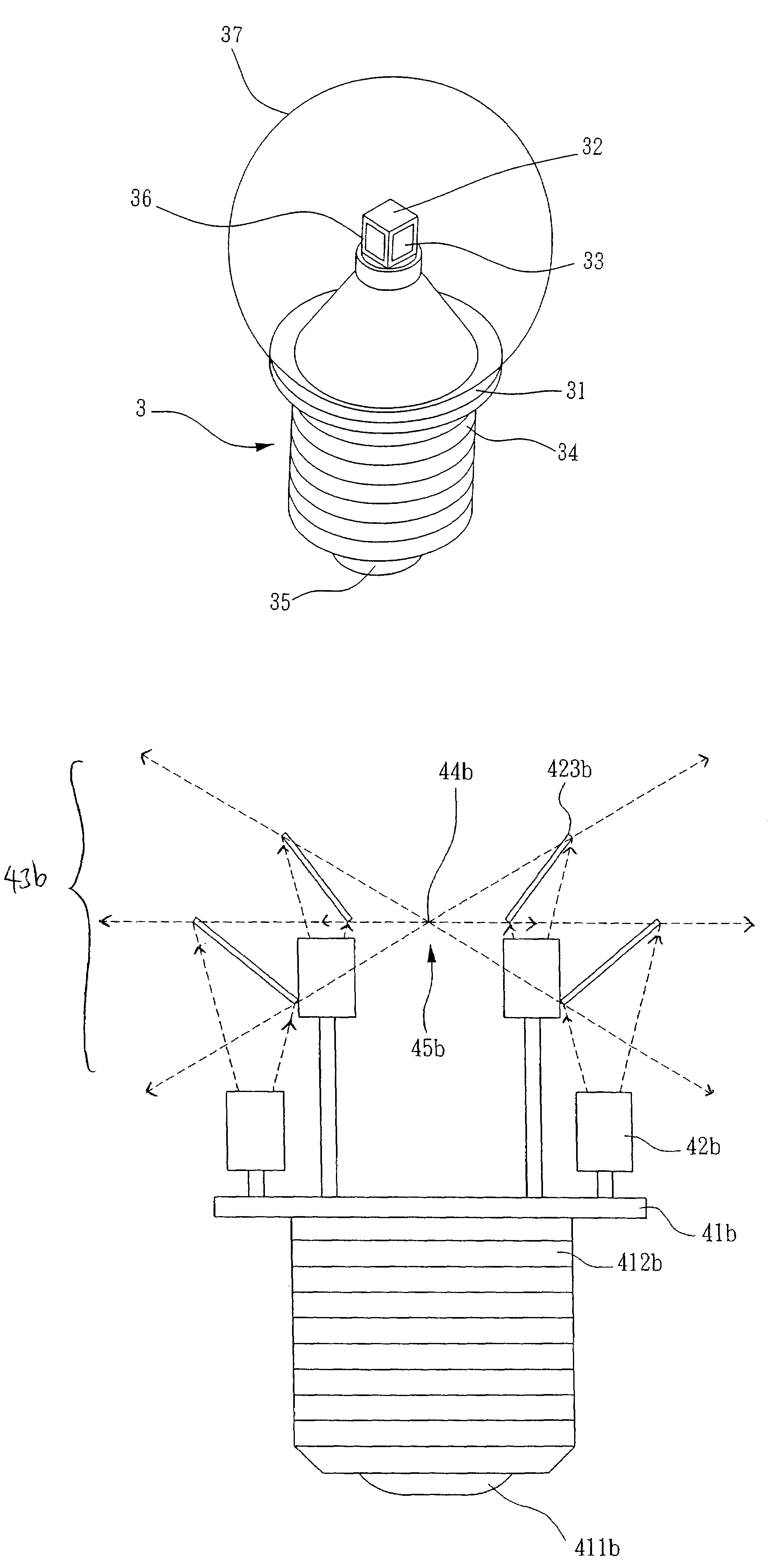
[0035]The present invention discloses lighting source structures that are provided with at least one lighting object which can be stimulated by energy (such as electricity) to generate visible or non-visible light. With the proper arrangement of a plurality of these lighting objects, the emitted light can be focused to act as a central lighting source to overcome the previous disadvantages experienced by the conventional lighting structures, such as short operation life, high consumption of electricity, and poor light focusing effect.

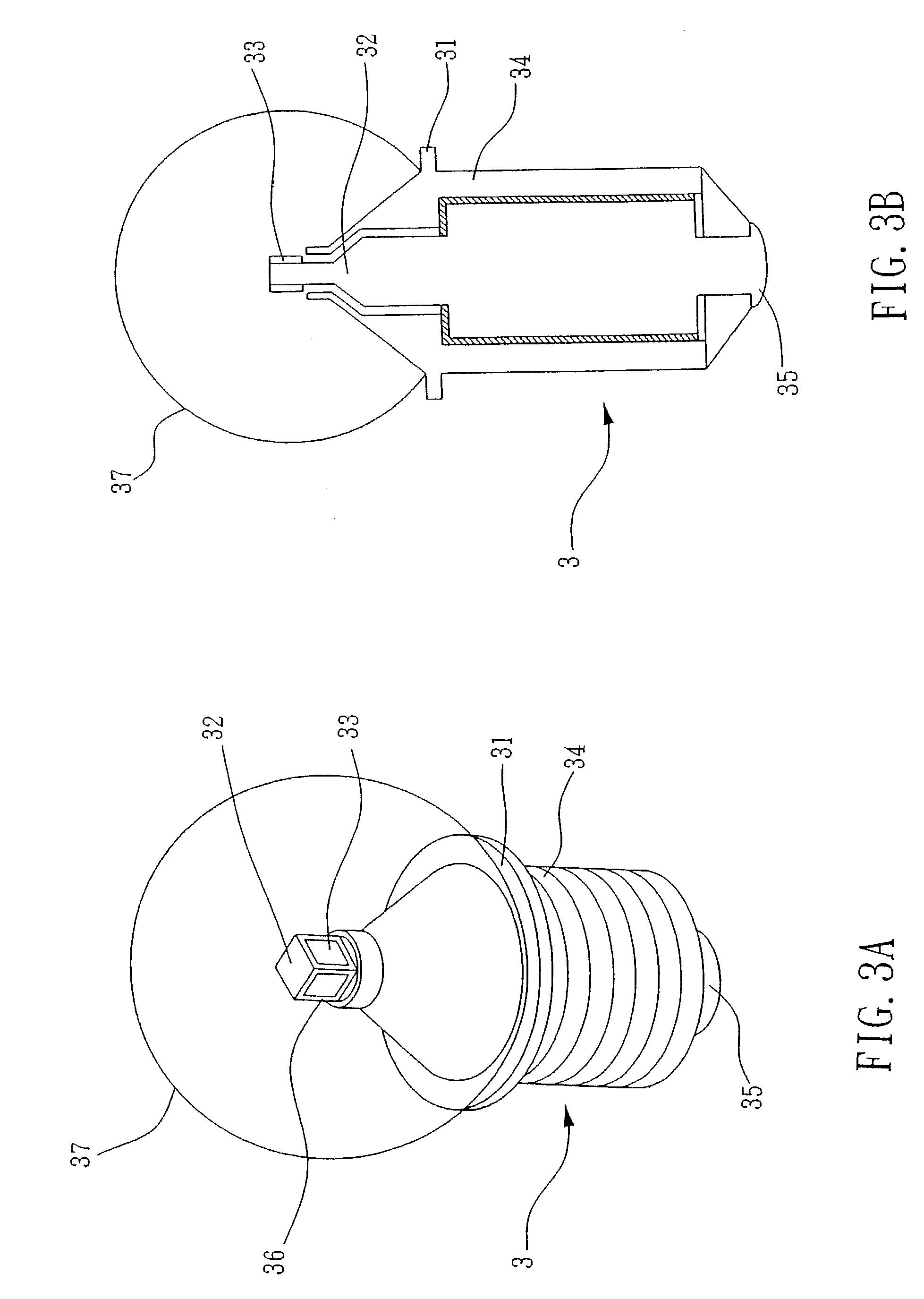
[0036]FIGS. 3A and 3B illustrate a first embodiment of a lighting source structure 3 according to the present inven...


PUM


Abstract

A lighting source structure has a base having at least one electrode coupled to a power source and a plurality of light sources, with each light source electrically coupled to the electrode to produce light when stimulated. The plurality of light sources are arranged on the base in a manner such that the light produced from the plurality of light sources is projected to form a lighted area that has a central focus point which is separate from the locations of each of the plurality of light sources.

Description

BACKGROUND OF THE INVENTION[0001]1. Field of the Invention[0002]The invention relates to a lighting source structure, and in particular, to a lighting source structure that replaces the filament of a conventional light bulb with a lighting object that produces light.[0003]2. Description of the Prior Art[0004]Light bulbs are an indispensable part of our daily lives. FIG. 1 illustrates a conventional bulb 1 that uses a filament 5 for generating light. The filament 5 is connected to a first electrode 2 and a second electrode 3. The first electrode 2 and the second electrode 3 are connected to a base 4 and to an electrical power source. When conducted, the electrical power source will supply electricity to the filament 5 to cause it to generate light and heat. Since the conventional bulb 1 has many disadvantages (e.g., large consumption of energy and short life), light emitting diodes (LED) have gradually begun to replace conventional bulbs as light sources.[0005]FIG. 2A illustrates a c...

Claims


Application Information

Patent Timeline
IPC IPC(8): F21V14/00F21K99/00H01L33/54
CPCF21K9/135F21V5/00F21V3/00F21V7/0008F21Y2101/02F21Y2111/001H01L25/0753F21Y2111/007H01L33/54F21K9/232F21K9/60F21Y2107/00F21Y2107/40F21Y2115/10H01L2224/48091H01L2224/48247H01L2924/0002H01L2924/00014
Inventor CHEN, TONY K. T.CHIU, MING-CHUNG
Owner QUARTON
Why Eureka
Try Eureka