Spade drill insert having helical margins

a technology of helical margins and inserts, which is applied in the direction of swing drills, manufacturing tools, wood boring tools, etc., can solve the problems of increased heat buildup on the insert, excessive exit chatter, and reducing the stability of the spade drill, so as to achieve the effect of increasing stability

Active Publication Date: 2006-03-14
ALLIED MASCH & ENG CORP
View PDF23 Cites 11 Cited by
  • Summary
  • Abstract
  • Description
  • Claims
  • Application Information

AI Technical Summary

Benefits of technology

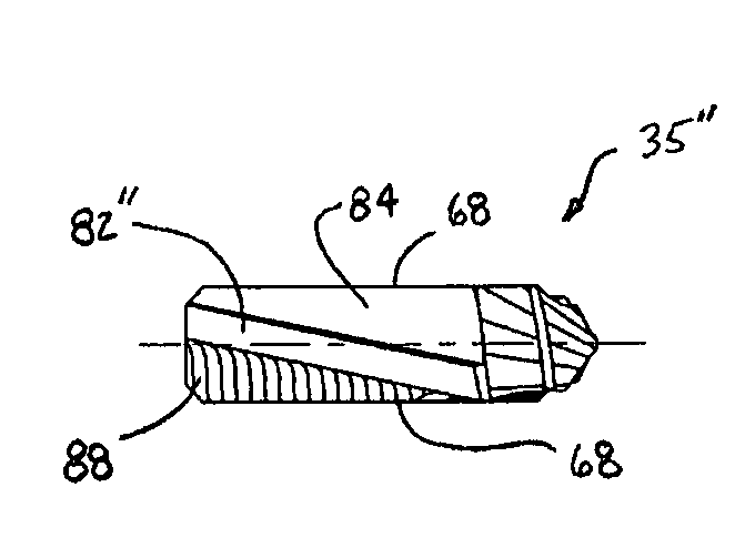
[0005]The spade drill of the present invention provides increased stability during drilling operations. This and other advantages are provided by a drill insert comprising a drill insert body having a first end opposite a second end, a first face side opposite and parallel to a second face side and a first land side opposite a second land side, the first and second land sides formed between the ends and the face sides; and a margin formed on a portion of each land side, the margin having a leading side and a trailing side, wherein at least one of the leading side and the trailing side is formed as a helix.

Problems solved by technology

One problem with prior art spade drill inserts is that only a small radial portion of the width side is in contact with the hole which reduces the stability of the spade drill and may cause excessive exit chatter when cutting select materials.
Another problem with some prior art spade drill inserts having large margins is that the margin surface area rubs against the side of the hole as the spade drill rotates which causes additional heat build up on the insert and may require reduced cutting speeds and may also shorten the life of the insert.

Method used


Image

  • Spade drill insert having helical margins
  • Spade drill insert having helical margins
  • Spade drill insert having helical margins

Examples


Embodiment Construction

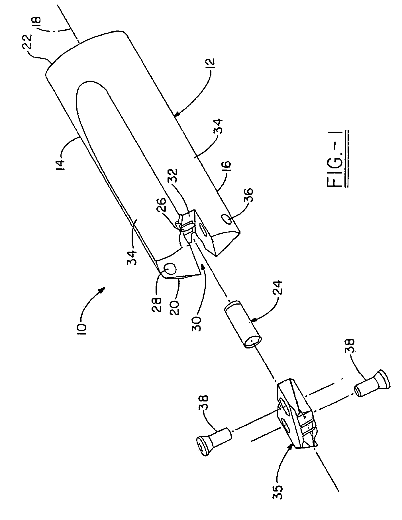
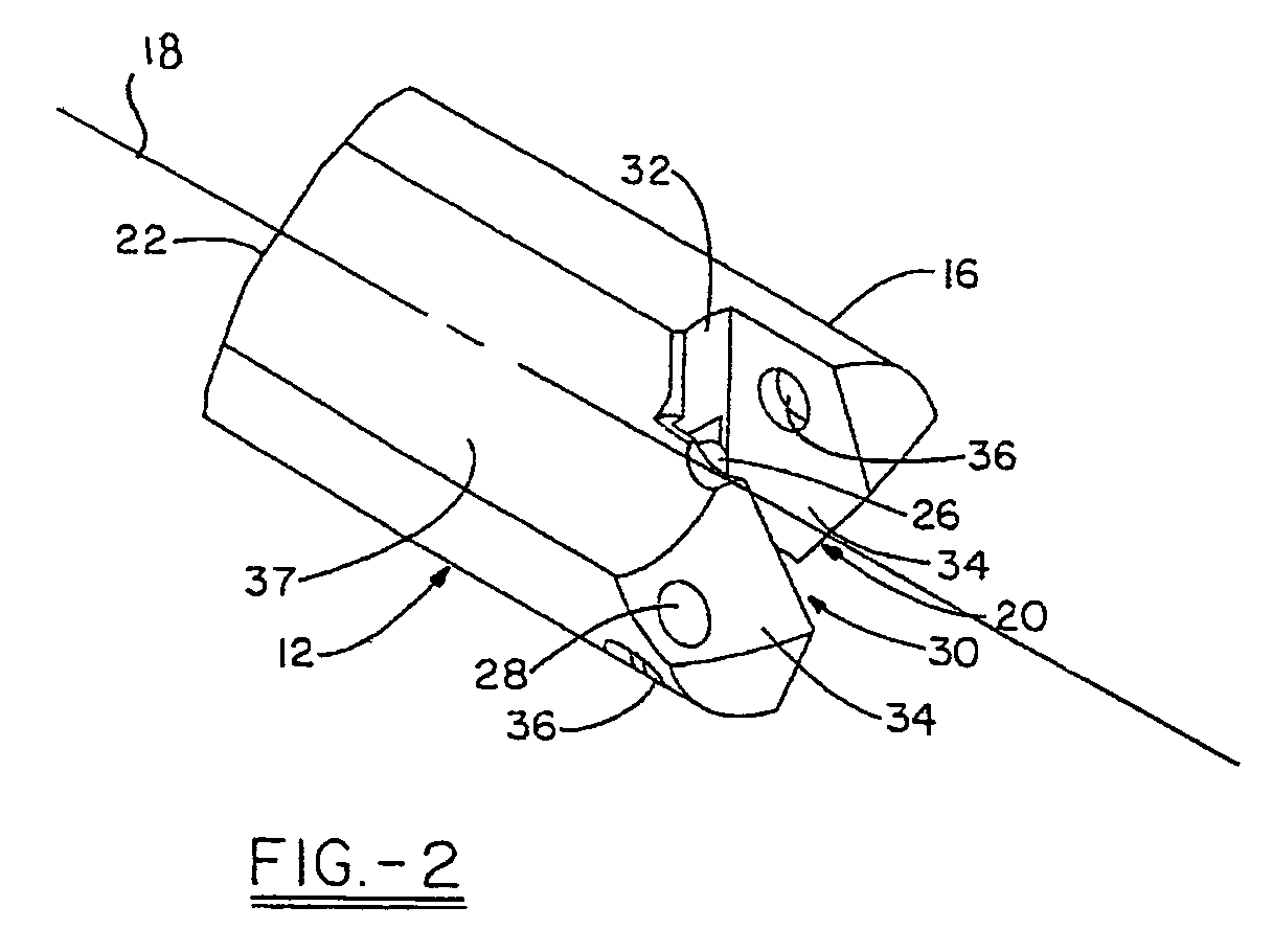
[0016]Turning now to a first embodiment of the invention, FIG. 1 illustrates a drill tool assembly 10 generally indicated. Drill tool assembly 10 comprises a holder 12, which has a body 14 and head portion 16 associated therewith. In the first embodiment, holder 12 has, in general, a cylindrical shape with a first end 20 and second end 22. As shown in FIG. 2, the first end 20 of holder 12 has a clamping or holder slot 30, which may extend across the entire diameter of the head portion 16 or, at least, over a center portion thereof at the general location of the rotational axis 18 of holder 12. The holder slot 30 has a bottom wall 32 positioned in substantially perpendicular orientation relative to the rotational axis 18 of the holder 12. In the embodiment shown, the assembly 10 may further include a locating boss or dowel pin 24, which is positioned precisely with respect to the axis 18 and extends from the bottom wall 32 of the holder slot 30. The pin 24 may be positioned within a ...


PUM

PropertyMeasurementUnit
widthaaaaaaaaaa
helix angleaaaaaaaaaa
speedaaaaaaaaaa

Abstract

A spade drill insert and drilling tool assembly is provided wherein the lands of the spade drill insert have helical margins which provide increased stability during cutting operations. The margin may have a helical trailing side or leading side, a parallel helical margin, or may also include a gullet or flute adjacent the helical margin.

Description

TECHNICAL FIELD[0001]This application claims the benefit of U.S. provisional patent application Ser. No. 60 / 518,205, filed Nov. 7, 2003, and is hereby incorporated by reference. The invention relates generally to a spade drill insert to be placed into a tool holder for boring holes into metals. More specifically, the invention relates to a spade drill insert having helical margins which provide increased stability during cutting operations.BACKGROUND OF THE INVENTION[0002]Drilling systems are frequently used to provide cylindrical holes in metallic workpieces. The cutting or boring action of the drill system may be carried out by an elongated, substantially cylindrical drilling tool, such as a combination of a tool holder and a spade drill insert, which is selectively attached thereto. Such an arrangement may then be used in an application wherein one end of the tool holder is securely mounted in a driving apparatus, which rotates the holder about its longitudinal axis. At the oppos...

Claims


Application Information

Patent Timeline
Patent Type & Authority Patents(United States)
IPC IPC(8): B23B51/02B23BB23B51/00B23D77/00B27G15/00
CPCB23B51/0009B23B2251/446B23B2251/48B23B2251/50Y10T408/90993Y10S408/713Y10T408/909B23B2270/30B23B51/00035B23B51/00B23B51/02B23B27/14
Inventor STOKEY, TIMOTHY G.FIEGL, GREGNUZZI, JOSEPH P.MAST, WENDELL E.
Owner ALLIED MASCH & ENG CORP
Why Eureka
Try Eureka