Industrial robot

Inactive Publication Date: 2006-03-14
ABB (SCHWEIZ) AG
View PDF9 Cites 14 Cited by
  • Summary
  • Abstract
  • Description
  • Claims
  • Application Information

AI Technical Summary

Benefits of technology

[0028]To lock all of the six degrees of freedom of the manipulated platform, a total of at least six (in a special case five) articulated rods are used. In this way, each articulated rod will only have to transmit tensile and compressive forces,

Problems solved by technology

The series connection of the arms of the SCARA robot, as well as in other robots with series-connected links, implies that the robot is given a large movable mass, that the robot structure is weak, that the accuracy is limited and that large motor torques are required to make fast movements.
This entails a clumsy design of the manipulator.
Both in the case of a two-dimensional and in the case of a three-dimensional manipulated platform according to the above-referred known manipulators, the problem arises that the arm that provides the movement of the robot in the vertical direction (in the z-direction) is influenced by large forces.
Especially unfavourable are forces that, in the outer end of the arm, act in an axial direction.
This entails the following disadvantages:The working r

Method used


Image

  • Industrial robot
  • Industrial robot
  • Industrial robot

Examples


Embodiment Construction

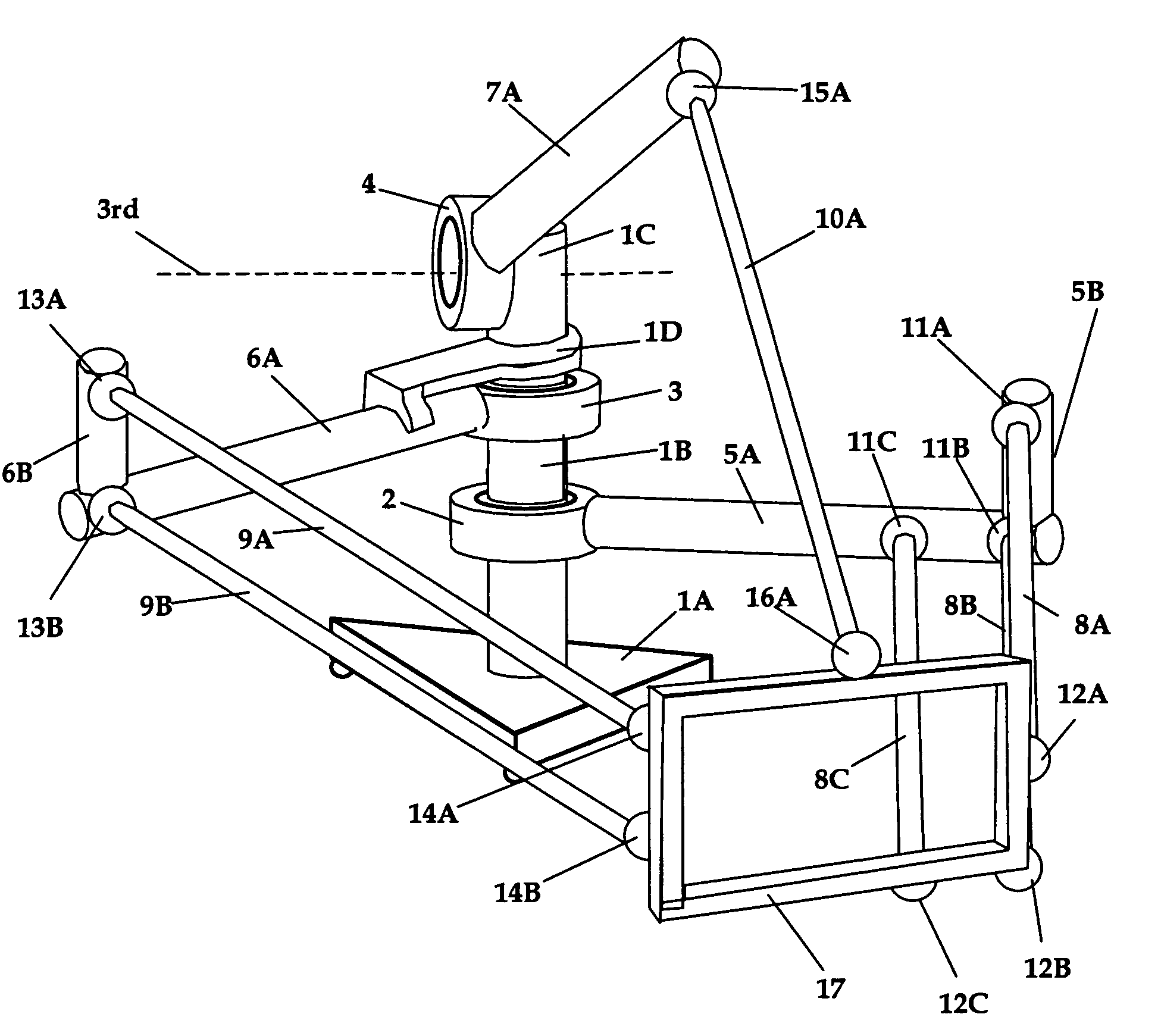
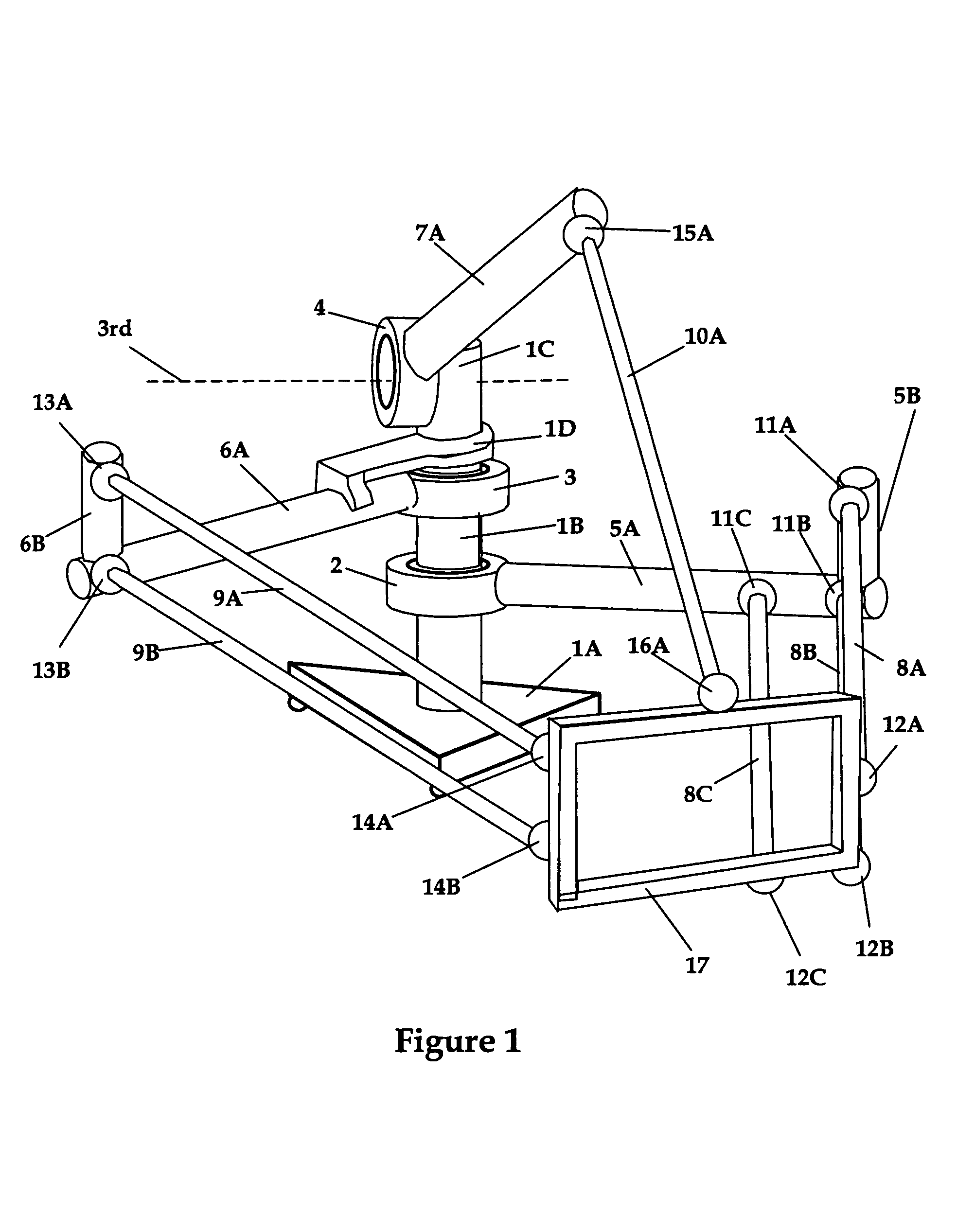
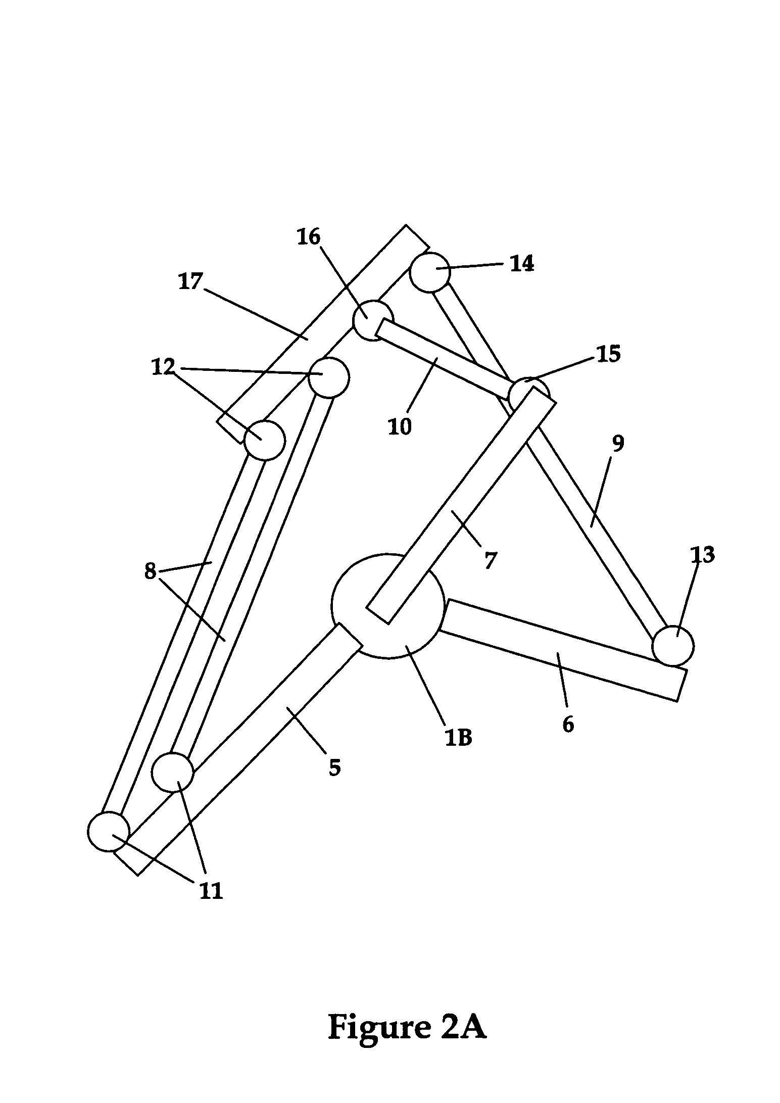
[0039]FIG. 1 shows a parallel-kinematic robot, which is a development of the known structures disclosed in, inter alia, U.S. Pat. No. 5,539,291. The robot is mounted on a foot 1A, on which a columnn 1B is secured. On this column there is arranged a first actuator 2 that pivots a first supporting arm 5 around a first axis, and a second actuator 3 that pivots a second supporting arm 6A around a second axis. Both axis are parallel to each other, whereby the two supporting arms are each pivoting in respective horizontal planes shown in the figure. The actuators 2 and 3 are of the rotary type with coinciding vertical axes of rotation. On the arm 6A, an element 1C is secured by means of a holder 1D, and on this element a third actuator 4 is mounted. This causes the actuator 4 to be rotated by the actuator 3 around the vertical axis of rotation of the actuator 3. The third actuator 4 pivots a third supporting arm 7A in a vertical plane shown in the figure. The third axis is thus oriented s...


PUM


Abstract

An industrial robot for movement of an object in space comprising a stationary platform, a movable platform adapted for supporting the object, and a first, a second and a third arm to which the platforms are joined. The first arm comprises a first actuator, a first supporting arm influenced by the first actuator and rotatable around a first axis, and a first linkage. The second arm comprises a second actuator, a second supporting arm influenced by the second actuator and rotatable around a second axis, and a second linkage. The third arm comprises a third actuator, a third supporting arm influenced by the third actuator and rotatable around a third axis, and a third linkage. The second supporting arm is freely mounted around a cross-beam that is arranged at right angles to the second axis.

Description

TECHNICAL FIELD[0001]The present invention relates to an industrial robot comprising a manipulator and control equipment where the manipulator has three arms, each arm having a linkage supporting a movable platform. The control equipment comprises drives and means including a microprocessor and software for driving and guiding the manipulator in the desired manner. To achieve the desired movement of the platform, the linkages comprise links or rods that are articulately connected between the platform and the arms. Each joint allows a movement in three degrees of freedom. The arms are fixed to stationary actuators that allow a movement in one degree of freedom. This movement comprises both rotation and translation. The task of the platform is to directly or indirectly support tools or objects for movement, measurement, processing, machining, joining, etc.BACKGROUND ART[0002]For movement and rotation of objects without changing the inclination of the objects, so-called SCARA-type robo...

Claims


Application Information

Patent Timeline
IPC IPC(8): B25J17/02B25J11/00B23Q1/54
CPCB23Q1/5462B25J17/0266Y10T74/20305Y10T74/20335Y10S414/13
Inventor BROGARDH, TORGNYWAPPLING, DANIELXIALONG, FENGHOLMGREN, BO
Owner ABB (SCHWEIZ) AG
Why Eureka
Try Eureka