Industrial robot

a robot and industrial technology, applied in the field of industrial robots, can solve the problems of limiting the speed of the robot, requiring expensive and energy-consuming actuators (motors), and weighing the robo

Active Publication Date: 2006-05-18
ABB (SCHWEIZ) AG
View PDF14 Cites 15 Cited by
  • Summary
  • Abstract
  • Description
  • Claims
  • Application Information

AI Technical Summary

Benefits of technology

[0056] It is also part of the inventive concept to form the third set of articulated rods (20, 21) either in the form of a parallelogram with two joints at each end of the articulated rods or in the form of a parallelepiped with two joints at each end of the articulated rods or in the form of an equilateral triangle or in the form of three articulated rods, of which at most two may be parallel. The articulated rods (20, 21) included in the third set of articulated rods are mounted by joints (29, 30) on the platform (31) such that a line between these joints becomes perpendicular to the above-described parallel lines for the joints between the first two sets (16, 17; 18, 19) of articulated rods and the platform (31). In that way, rotation of the platform (31) is avoided when the platform is manipulated.

Problems solved by technology

This serial construction of the robot results in the following problems: The robot becomes heavy, which limits its speed and which necessitates expensive and energy-consuming actuators (motors).
If, in addition, the robot is to be mounted as a slave on a master manipulator in order, for example, to guide the robot into narrow spaces, a heavy slave-type robot gives a still heavier and more expensive master manipulator.
The robot becomes pliant and when objects or tools are moved, a undesired oscillating motion is obtained along the path along which the movement is to be made, and when the movement is to be stopped, so-called overshoots arise.
This problem is increased further in case of a master / slave configuration, whereby also the performance of the master manipulator is deteriorated.
The robot becomes resilient when forces are to be generated between the tool and the object, which is impaired in a master / slave configuration.
For the serially mounted movable actuators with associated measurement sensors, movable cabling is required, which reduces the reliability of the serially kinematic robots.
It is difficult to obtain a high accuracy of the robot without providing very expensive solutions with precision components and precision assembly of the robot.
For this reason, the robot cannot be designed for a working range in the form of a sphere or an ellipsoid.
However, this structure provides a working range that is barely half an ellipsoid and that is therefore not sufficient to build a robot capable of working in all directions with a working range corresponding to a whole ellipsoid or sphere.
Since the legs are working in different planes, all the axes of rotation of the driving motors will have different directions, which makes it impossible to have two parallel or coinciding motor shafts.
In several applications, it is desirable to use linear actuators without pivoting arms, which is not possible with legs working in different planes.

Method used


Image

  • Industrial robot
  • Industrial robot
  • Industrial robot

Examples


Embodiment Construction

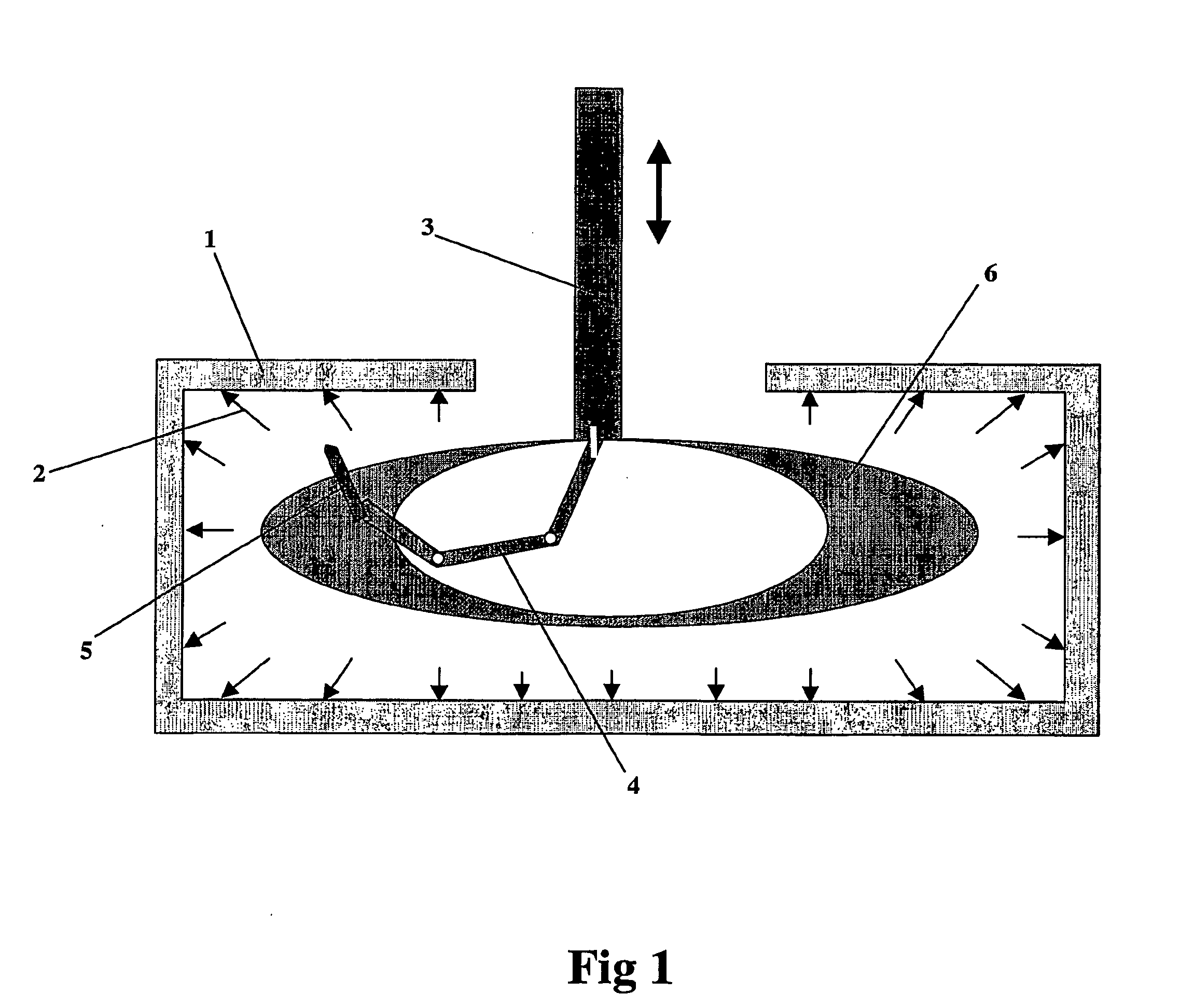
[0066]FIG. 1 schematically shows a frequently occurring case when using industrial robots in a more or less closed space. The space is limited according to the figure by walls 1, on the inside of which operations such as welding, painting, grinding, cutting, measurement, machining, assembly, etc., are to be carried out, as indicated by the arrows 2. To move the robot 4 into the space in question, there is used an external manipulator with a column structure 3, which is capable of being manipulated at least up and down. To enable the robot to move the tool 5 to the positions and orientations shown by the arrows 2, a spherically or elliptically shaped working range 6 for the robot is required. In addition, the kinematics of the robot should be designed such that the tool holder, on which the tool 5 is mounted, points approximately radially outwards from the spherical / elliptical working range 6. In that way, less demands will be made on the accessibility of the wrist that is to direct ...


PUM


Abstract

An industrial robot for moving an object in space comprising a stationary platform, a movable platform arranged for supporting the object, and a first, a second and a third arm to which the platforms are joined. The first arm comprises a first actuator, a first supporting arm influenced by the first actuator and being rotatable around a first axis, and a first linkage. The second arm comprises a second actuator, a second supporting arm influenced by the second actuator and being rotatable around a second axis, and a second linkage. The third arm comprises a third actuator, a third supporting arm influenced by the third actuator and being rotatable around a third axis, and a third linkage. The first and third axes are arranged in parallel and the second supporting arm is freely journalled around a transverse axis that is substantially arranged at right angles to the second axis.

Description

TECHNICAL FIELD [0001] The present invention relates to an industrial robot comprising a manipulator and control equipment where the manipulator has three arms, each arm having a linkage supporting a movable platform. The control equipment comprises drives and means including a microprocessor and software for driving and guiding the manipulator in the desired manner. To achieve the desired movement of the platform, the linkages comprise links or rods that are articulately connected between the platform and the arms. Each joint allows a movement in three degrees of freedom. The arms are fixed to stationary actuators that allow a movement in one degree of freedom. This movement comprises both rotation and translation. The task of the platform is to directly or indirectly support tools or objects for movement, measurement, processing, machining, joining, etc. BACKGROUND ART [0002] A robot comprising more than one arm and where at least two arms each form chains of joints between the ac...

Claims


Application Information

Patent Timeline
Patent Type & Authority Applications(United States)
IPC IPC(8): B25J9/10B23Q1/54B25J17/02
CPCB23Q1/5462Y10T74/20329B25J9/0072B25J17/0266
Inventor SKUTBERG, HANSVALLIN, ASABROGARDH, TORGNYANDREASSON, MATHILDALUNDBERG, IVAN
Owner ABB (SCHWEIZ) AG
Why Eureka
Try Eureka