Eureka AIR delivers breakthrough ideas for toughest innovation challenges, trusted by R&D personnel around the world.

Turbomachine with cooled ring segments

a technology of ring segments and turbines, which is applied in the direction of machines/engines, stators, liquid fuel engines, etc., can solve the problems of affecting the cooling effect of the ring segments, the tenon and mortise connection used between the casing and each ring segment is not perfect, and the cooling effect of the ring segment is detrimental to the cooling effect of the ring segment, so as to achieve accurate positioning

Active Publication Date: 2006-03-14
SN DETUDE & DE CONSTR DE MOTEURS DAVIATION S N E C M A
View PDF23 Cites 44 Cited by
  • Summary
  • Abstract
  • Description
  • Claims
  • Application Information

AI Technical Summary

Benefits of technology

[0017]Advantageously, the fastening device is of much simpler design than that of the system described previously, insofar as they no longer require very accurately dimensioned hooks and clips, but instead consist essentially of a simple clamping screw.
[0018]Furthermore, the radial clamping screw arrangement allows the ring segment to be very accurately positioned, axially and tangentially, relative to the turbine casing, thus considerably reducing cooling air leakage between these elements. In this way, the turbine casing has improved thermal protection and the ring segments can be properly cooled.
[0019]The fastening device used in the invention also simplify installation and reduce costs in comparison to those of the prior art described above and shown in FIG. 1.
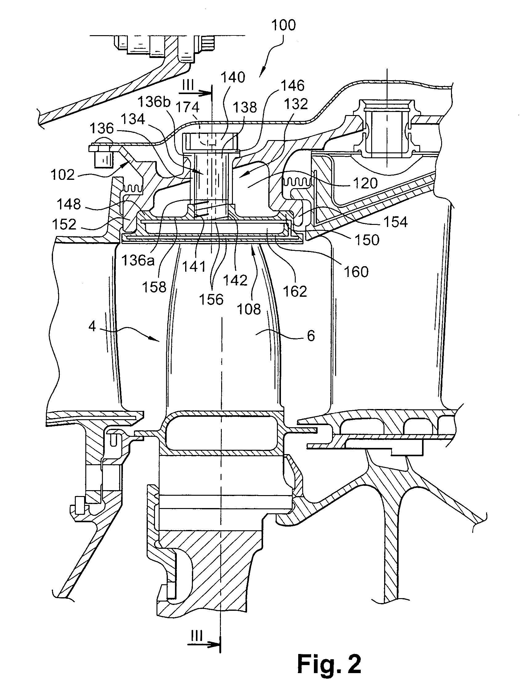
[0020]The fact of providing one or more airways through the screw also allows the fastening device of each ring segment to be advantageously combined with the means required for routing cooling air to the cooling cavity of the ring concerned. With such an arrangement, the cooling air drawn from the desired location, such as a compressor of the turbomachine, for example, enters a radial outer end of the airway, then passes through the airway and is then discharged through a radial inner end into the main cooling cavity where it thus serves to cool the ring segment.
[0023]For each ring segment, the spacer preferably forms a limit stop for that same ring segment, in such a way as to position it radially with respect to the casing. Thus, with such a configuration, a single spacer judiciously positioned on the casing would enable the ring segment to be very accurately positioned relative to it in the axial, tangential and radial directions.

Problems solved by technology

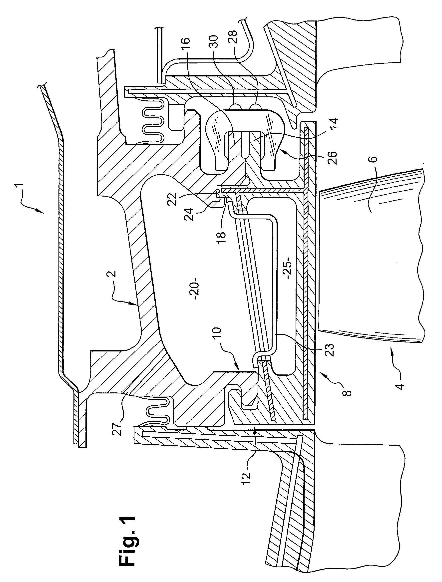
The system for attaching the ring segments to the casing is therefore of very complex design and thus relatively costly.
Moreover, the tenon and mortise connection used between the casing and each ring segment does not provide a perfect seal.
Leaking therefore occurs between these two elements, which naturally has a detrimental effect on the cooling of the ring segments and the thermal protection of the turbine casing.
From the above, therefore, it is clear that the means necessary for directing the air to the cooling cavity, such as the cooling openings formed in the casing, serve to further complicate the design of the turbomachine.

Method used


Image

  • Turbomachine with cooled ring segments
  • Turbomachine with cooled ring segments
  • Turbomachine with cooled ring segments

Examples


Embodiment Construction

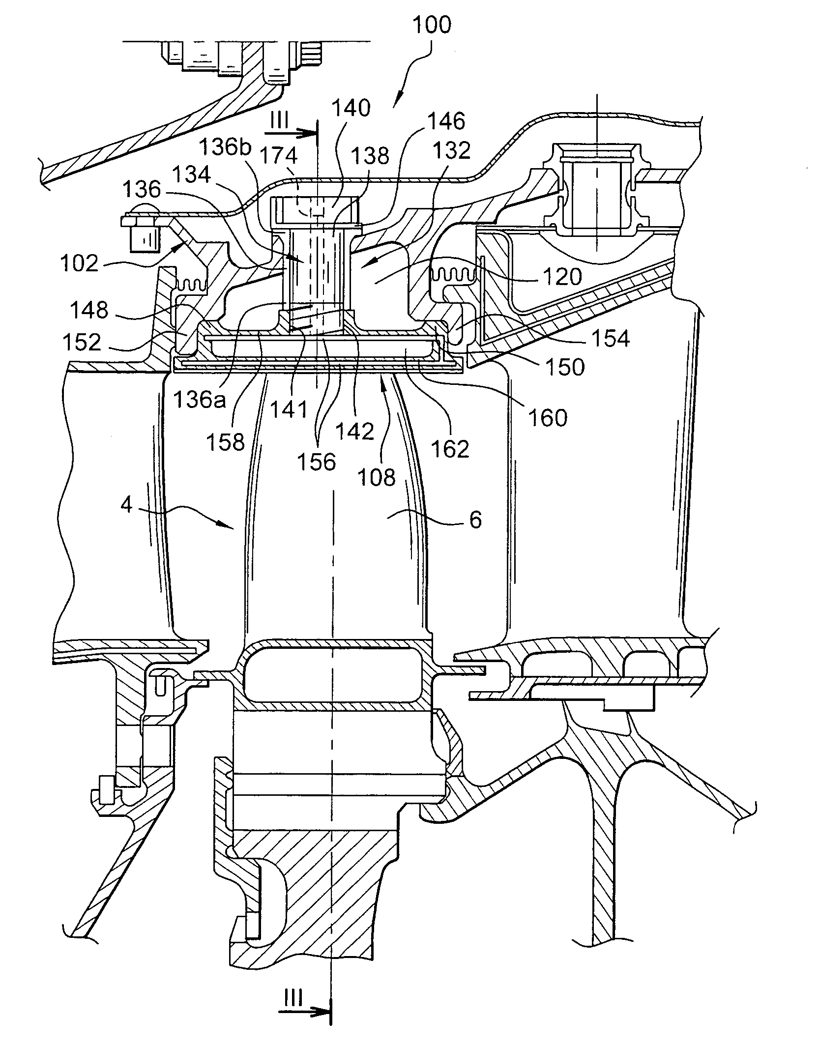
[0035]Referring to FIGS. 2 and 3, these show a partial representation of a turbomachine 100 according to a first preferred embodiment of the present invention.

[0036]The turbomachine comprises a casing 102 as well as a rotor 4 with blades 6. Therefore, as the invention finds particular application when applied to a turbine of the turbomachine 100, we will consider for the remainder of the description that the section shown in FIGS. 2 and 3 corresponds to a high pressure turbine of this turbomachine and that the casing 102 and the rotor 4 thus correspond respectively to a turbine casing 102 and a turbine rotor 4 fitted with blades 6. It is noted that this choice of application of the invention to a turbine (preferably the high pressure turbine subjected to high thermal stresses) will be adopted for all of the preferred embodiments shown in FIGS. 2 to 6, and described below.

[0037]Obviously, as has already been stated above, the invention could equally be applied to a compressor of the ...


PUM


Abstract

A turbomachine includes a casing, a rotor, and a plurality of cooled ring segments installed between the casing and the rotor, each ring segment containing a main cooling cavity and being attached to the casing by a fastening device. The fastening device can include a clamping screw positioned more or less radially and pinning the ring segment against the casing. The clamping screw is crossed through by a cooling airway that communicates with the main cooling cavity of the ring segment.

Description

TECHNICAL FIELD[0001]This invention pertains generally to turbomachines with cooled ring segments.[0002]More specifically, the invention relates to a turbomachine comprising a casing, a rotor and a plurality of cooled ring segments installed between the casing and the rotor, each of these sectors being provided with at least one cooling cavity.[0003]The ring segments can equally well be turbine (preferably high pressure turbine) ring segments, or compressor ring segments. On this account, it is specified that the invention finds particular (but not exclusive) application in the turbines of turbomachines, insofar as the high surrounding thermal stresses require the presence of such cooled ring segments.PRIOR ART[0004]FIG. 1 shows a partial view of a portion of a high pressure turbine of a turbomachine 1 according to the prior art, as described in document FR-A-2 800 797.[0005]As can be seen in this figure, the high pressure turbine comprises a turbine casing 2, as well as a rotor 4, ...

Claims


Application Information

Patent Timeline
IPC IPC(8): F01D25/12F01D1/00F01D9/04F01D11/08F01D25/24F02C7/18F02C7/28
CPCF01D9/04F01D25/246F01D11/08
Inventor MARCHI, MARCRODRIGUES, PAULROSSET, PATRICETAILLANT, JEAN-CLAUDEARILLA, JEAN-BAPTISTE
Owner SN DETUDE & DE CONSTR DE MOTEURS DAVIATION S N E C M A
Why Eureka
Eureka Blog
Learn More