Compound electrical connector

a technology of electrical connectors and connectors, applied in the direction of coupling device details, coupling device connections, electric discharge lamps, etc., can solve the problem and achieve the effect of saving space in electronic devices

Inactive Publication Date: 2006-03-14
CHENG UEI PRECISION IND CO LTD
View PDF6 Cites 12 Cited by
  • Summary
  • Abstract
  • Description
  • Claims
  • Application Information

AI Technical Summary

Benefits of technology

[0009]In the present invention, the audio jack, the power jack and the radio frequency jack are integrated in the compound electrical connector for facilit

Problems solved by technology

Additionally, the compound electrical connec

Method used


Image

  • Compound electrical connector
  • Compound electrical connector
  • Compound electrical connector

Examples


Embodiment Construction

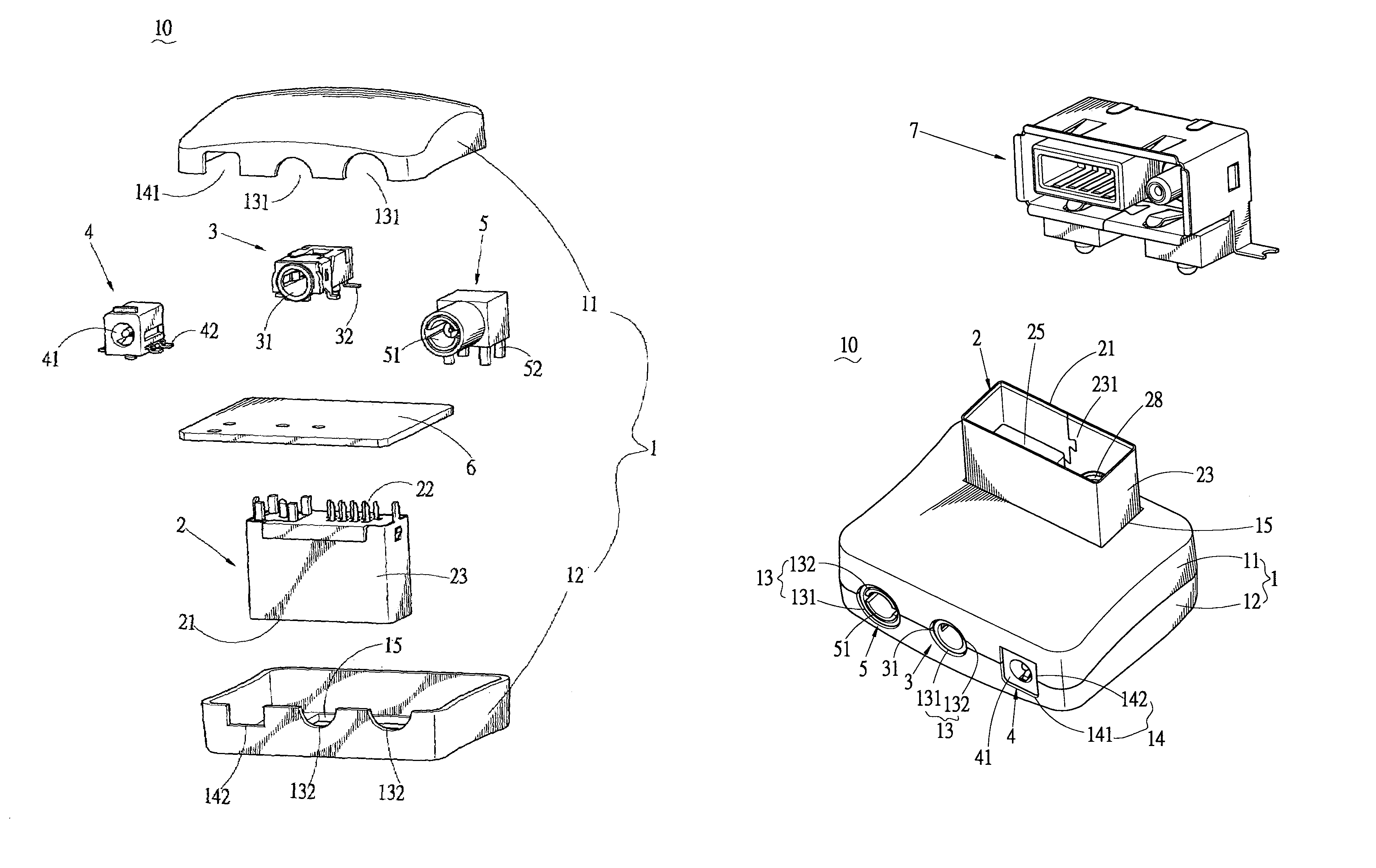
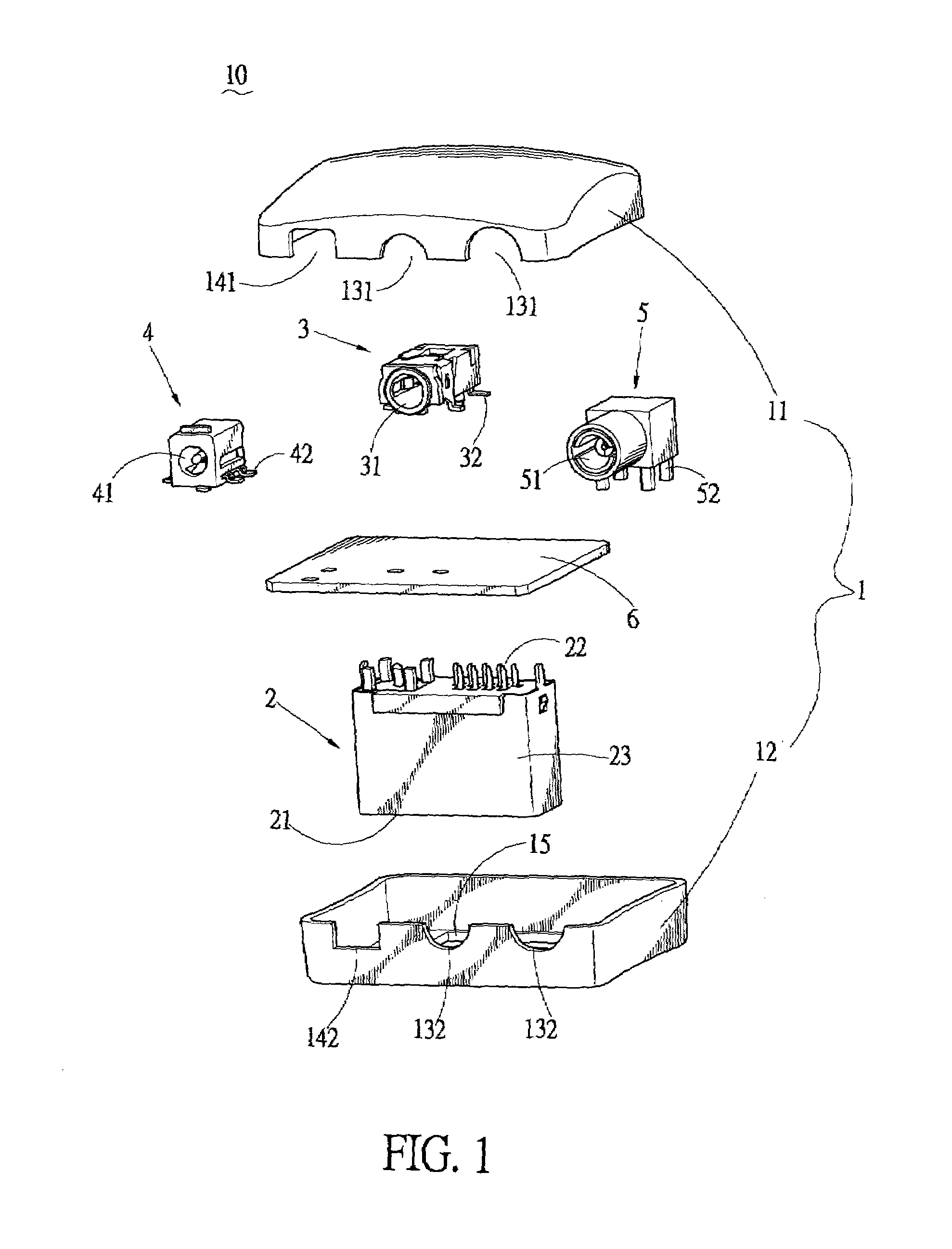
[0016]Referring to FIGS. 1 and 3, a compound electrical connector 10 comprises an insulation cover 1. The insulation cover 1 includes an upper cover 11 and a lower cover 12. The upper and lower covers 11, 12 are assembled to be the insulation cover 1 by means of ultrasonic soldering. A cutout 15 is defined on the bottom surface of the lower cover 12. The insulation cover 1 further has three cavities 13, 14 formed on one lateral side thereof, in which two cavities 13 are circular and defined respectively as the first cavity and the third cavity, another cavity 14 is square and defined as the second cavity (as shown in FIG. 3). Each of the two circular cavities 13 consists of a pair of semicircular notches 131, 132 disposed respectively on the upper cover 11 and the lower cover 12 and in symmetric configuration. The square cavity 14 consists of a pair of rectangular notches 141, 142 disposed respectively on the upper cover 11 and the lower cover 12 and in symmetric configuration. Acco...


PUM


Abstract

The present invention provides a compound electrical connector comprising a plug connector, an audio jack, a power jack and a radio frequency jack, together with a printed circuit board assembled in an insulation cover. The insulation cover has three cavities formed on one side thereof for receiving the three jacks respectively. Each of the audio jack, the power jack and the radio frequency jack has a contacting portion received respectively in one of the corresponding cavities of the insulation cover for contacting with complementary connectors and a soldering portion being soldered to a printed circuit board. The plug connector comprises a contacting portion protruded out from another side of the insulation cover for contacting with a complementary socket connector, and a soldering portion being soldered to the printed circuit board. Therefore, the compound electrical connector facilitates installing the jacks with different functions connector to an electronic device and saves space in the electronic device.

Description

BACKGROUND OF THE INVENTION[0001]1. Field of the Invention[0002]The present invention relates generally to a compound electrical connector, and more especially to a compound electrical connector capable of integrating a plug connector, an audio jack, a power jack and a radio frequency (RF) jack with an insulation cover.[0003]2. The Related Art[0004]With the development of variety of electronic peripheral devices, the transmission interface is achieved by various means. Therefore, various electrical connectors having different structures and functions are employed widely as transmission interfaces for satisfying various needs of different hardware devices. In general, electrical connectors are mounted individually on the edge of a printed circuit board (PCB) in an electronic device, and arranged in juxtaposed or parallel manner. However, the arrangement of the electrical connectors occupies too much inner space of the electronic device, and brings some hindrance to the miniaturizatio...

Claims


Application Information

Patent Timeline
IPC IPC(8): H01R25/00
CPCH01R27/02H01R13/447H01R2201/18H01R13/6658
Inventor LAI, MING CHUNLUO, JIZU
Owner CHENG UEI PRECISION IND CO LTD
Why Eureka
Try Eureka