Instruments and methods for stabilization of bony structures

a technology of bony structure and instruments, applied in the field of surgical instruments, can solve the problems of skin and tissue surrounding the surgical site to be cut, removed, scarring of the tissue, and tissue to become infected, and achieve the effect of minimal invasive and stabilizing the bony structur

Inactive Publication Date: 2006-03-14
WARSAW ORTHOPEDIC INC
View PDF74 Cites 416 Cited by
  • Summary
  • Abstract
  • Description
  • Claims
  • Application Information

AI Technical Summary

Benefits of technology

[0020]One object of the present invention is to provide minimally invasive techniques and instruments for stabilizing a bony structure in an animal subject.

Problems solved by technology

One problem associated with the above described stabilization structures is that the skin and tissue surrounding the surgical site must be cut, removed, and / or repositioned in order for the surgeon to access the location where the stabilization device is to be installed.
This repositioning of tissue causes trauma, damage, and scarring to the tissue.
There are also risks that the tissue will become infected and that a long recovery time will be required after surgery for the tissue to heal.

Method used


Image

  • Instruments and methods for stabilization of bony structures
  • Instruments and methods for stabilization of bony structures
  • Instruments and methods for stabilization of bony structures

Examples


Embodiment Construction

[0049]For the purposes of promoting an understanding of the principles of the invention, reference will now be made to the embodiments illustrated in the drawings and specific language will be used to describe the same. It will nevertheless be understood that no limitation of the scope of the invention is thereby intended. Any such alterations and further modifications in the illustrated devices, and such further applications of the principles of the invention as illustrated herein are contemplated as would normally occur to one skilled in the art to which the invention relates.

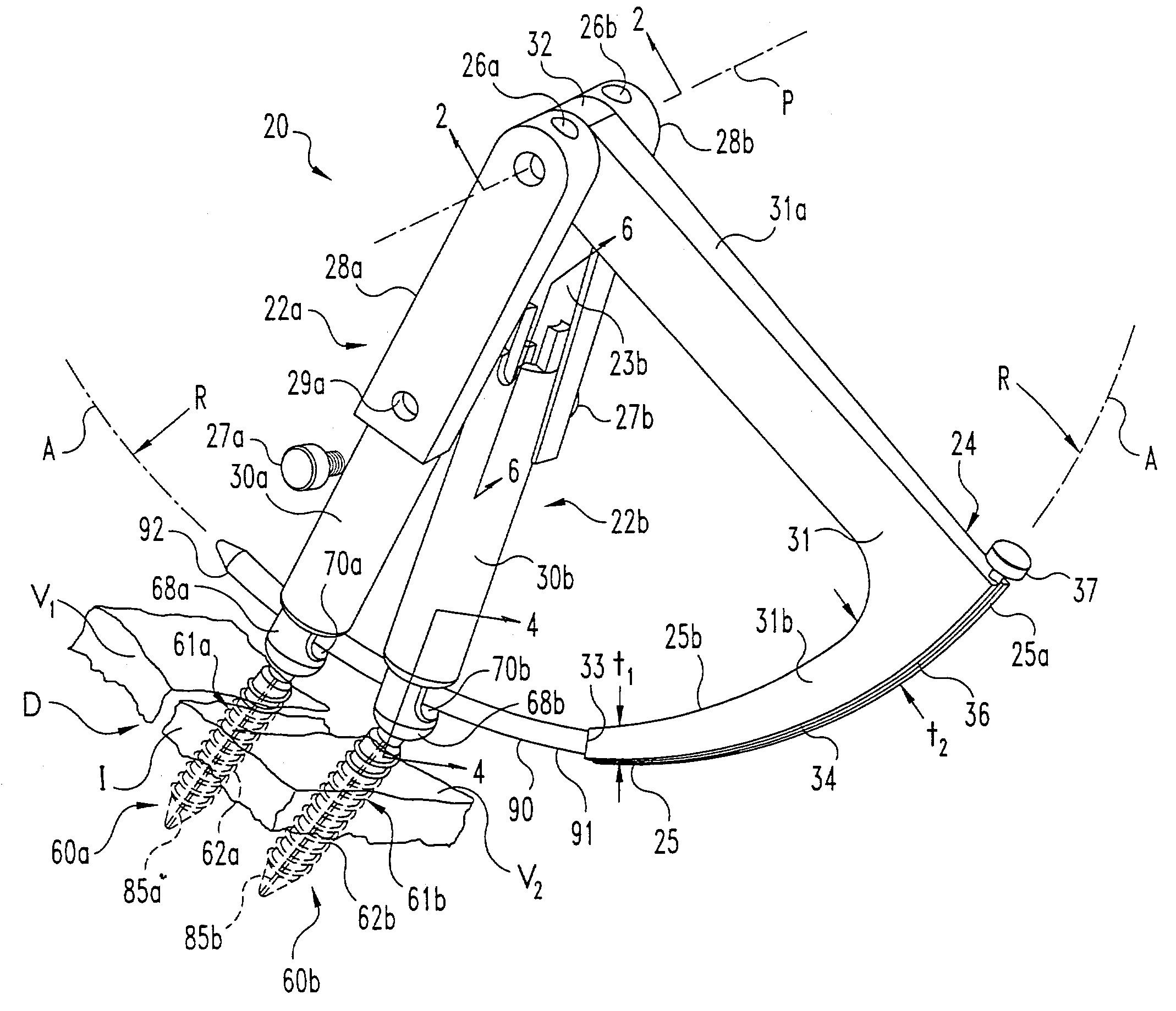
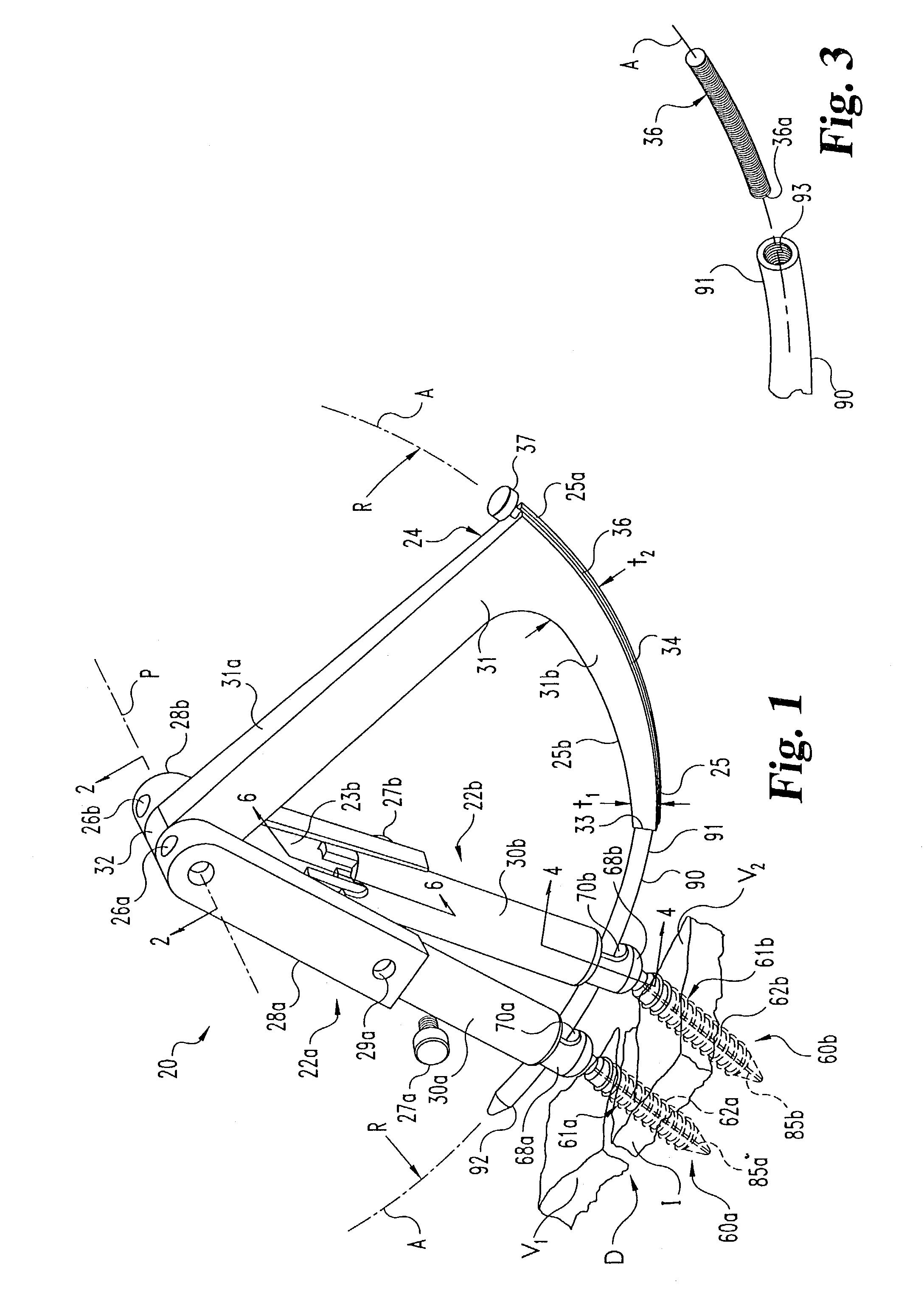
[0050]The present invention is directed to instruments and methods for insertion of a brace for connection with anchors engaged to bony parts of the body. Referring to FIG. 1, connecting element or brace 90 is preferably an elongated rod or shaft curved along its length between a connecting end 91 and an insertion end 92 with a radius of curvature R. However, it should be understood that the present invention...


PUM


Abstract

The present invention relates to a brace installation instrument placement that is mounted to anchors secured in an animal subject. The installation instrument includes anchor extensions coupled to the anchors. The instrument is movable with respect to the anchors to position a brace in a position more proximate the anchors. The brace can be indexed for insertion at a predetermined orientation with respect to the installation instrument. Methods and techniques for using the installation instrument are also provided.

Description

CROSS-REFERENCE TO RELATED APPLICATIONS[0001]The present application is a continuation application of U.S. patent application Ser. No. 10 / 263,522 filed on Oct. 3, 2002, which is a divisional application of U.S. patent application Ser. No. 09 / 616,581 filed on Jul. 14, 2000, now issued as U.S. Pat. No. 6,530,929, which claims the benefit of the filing dates of Provisional Application Ser. No. 60 / 186,729, filed Mar. 3, 2000 and Provisional Application Ser. No. 60 / 160,489, filed Oct. 20, 1999. The referenced applications are each incorporated herein by reference in their entirety.BACKGROUND OF THE INVENTION[0002]The present invention generally relates to surgical instruments and methods for use of the same, and more particularly, but not exclusively, relates to instruments and methods for stabilizing bony structures.[0003]The use of various devices and methods for stabilizing bone structures have been used for many years. For example, the fracture of an elongated bone, such as a femur o...

Claims


Application Information

Patent Timeline
Patent Type & Authority Patents(United States)
IPC IPC(8): A61B17/90A61B17/58A61B17/00A61B17/16A61B17/88
CPCA61B17/1671A61B17/7089A61B17/7086A61B17/8872A61B17/88A61B17/00234A61B2017/90A61B17/90A61B17/7038A61B17/8897A61B2017/681
Inventor SHERMAN, MICHAEL C.FOLEY, KEVIN T.JUSTIS, JEFF R.
Owner WARSAW ORTHOPEDIC INC
Why Eureka
Try Eureka