Expandable stent apparatus and method

a stent and apparatus technology, applied in the field of expandable stents, can solve the problems of unsuitability for intra-cranial use, and achieve the effect of enhancing expansion

Inactive Publication Date: 2006-03-14
EV3
View PDF9 Cites 15 Cited by
  • Summary
  • Abstract
  • Description
  • Claims
  • Application Information

AI Technical Summary

Benefits of technology

[0013]The self expanding rolled sheet stent is suitable for use in the intra-cranial arteries. The rolled sheet is made of Elgiloy™, nitinol, stainless steel, plastic or other suitable material, and is imparted with resilience to urge outward expansion of the roll to bring the rolled stent into contact with the inner wall of a diseased artery. The rolled sheet is adapted for easy insertion and non-deforming radial flexibility to facilitate tracking along the tortuous insertion pathways into the brain. In some embodiments, as much of the material of the stent is removed as is consistent with eventual creation of a solid walled stent upon unrolling of the stent within the blood vessel. The unrolled stent may be two or more layers of Elgiloy™, thus providing radial strength for the stent and creating at least a slight compliance mismatch between the stent and the blood vessel, thereby creating a seal between the stent and the blood vessel wall. For placement, the stent is tightly rolled upon or captured within the distal tip of an insertion catheter. The release mechanism is extremely low profile (3 Fr or less), and permits holding the rolled stent in a tight roll during insertion and permits atraumatic release when in the proximity of the site of arterial disease, without completely occluding the vessel with the deployment catheter. The stent can be placed in the intra-cranial blood vessels (arteries and veins) of a patient to accomplish immediate and complete isolation of an aneurysm and side branches from the circulatory system. The stent can be placed so as to partially occlude or modify blood flow into an aneurysm. The stent can be placed so as to allow for injection of coils (GDC coils or Gianturco coils) or embolic material into an aneurysm and prevent wash-out of the coils or embolic material. The stent may be placed across a target site such as an aneurysm neck, origin of a fistula, or branch blood vessels feeding a tumor in order to redirect the flow of blood away from the target. It can be used as a stand alone device which is left in the intra-cranial artery permanently, or it may be used as a temporary device which allows for immediate stabilization of a patient undergoing rupture of a blood vessel an aneurysm or awaiting open skull surgery for clipping or resection of an aneurysm. The stent can be used for stabilization and isolation of a vascular defect during surgery of the vascular defect. Another advantage of this type of stent is that it can be wound down should repositioning be required prior to full release. It is possible to rewind and reposition or remove the device using a crooked rotating wire or other grasping tools.
[0015]In preferred embodiments, a biocompatible sheeted material is wrapped around a retaining wire to produce the compacted configuration, and the retaining wire is rotated to maintain the compacted configuration during insertion of the stent into a patient. The rotation is continued while the stent positioned, and then the rotation is stopped or slowed to permit expansion of the sheet. Counter rotation may be used to enhance expansion, if desired.

Problems solved by technology

The physical characteristics of prior art balloon expandable stents and self expanding stents make them clearly unsuitable for intra-cranial use, because of their delivery profile, their lack of flexibility and their tendency to temporarily occlude the vessel during deployment.
Palmaz stents, Palmaz-Schatz™ stents, Wallstents, Cragg stents, Strecker stents and Gianturco stents and other stents are too rigid to allow placement in the cerebral blood vessels, some require a balloon for deployment, and all are too open to occlude or prevent blood flow into an aneurysm.

Method used


Image

  • Expandable stent apparatus and method
  • Expandable stent apparatus and method
  • Expandable stent apparatus and method

Examples


Embodiment Construction

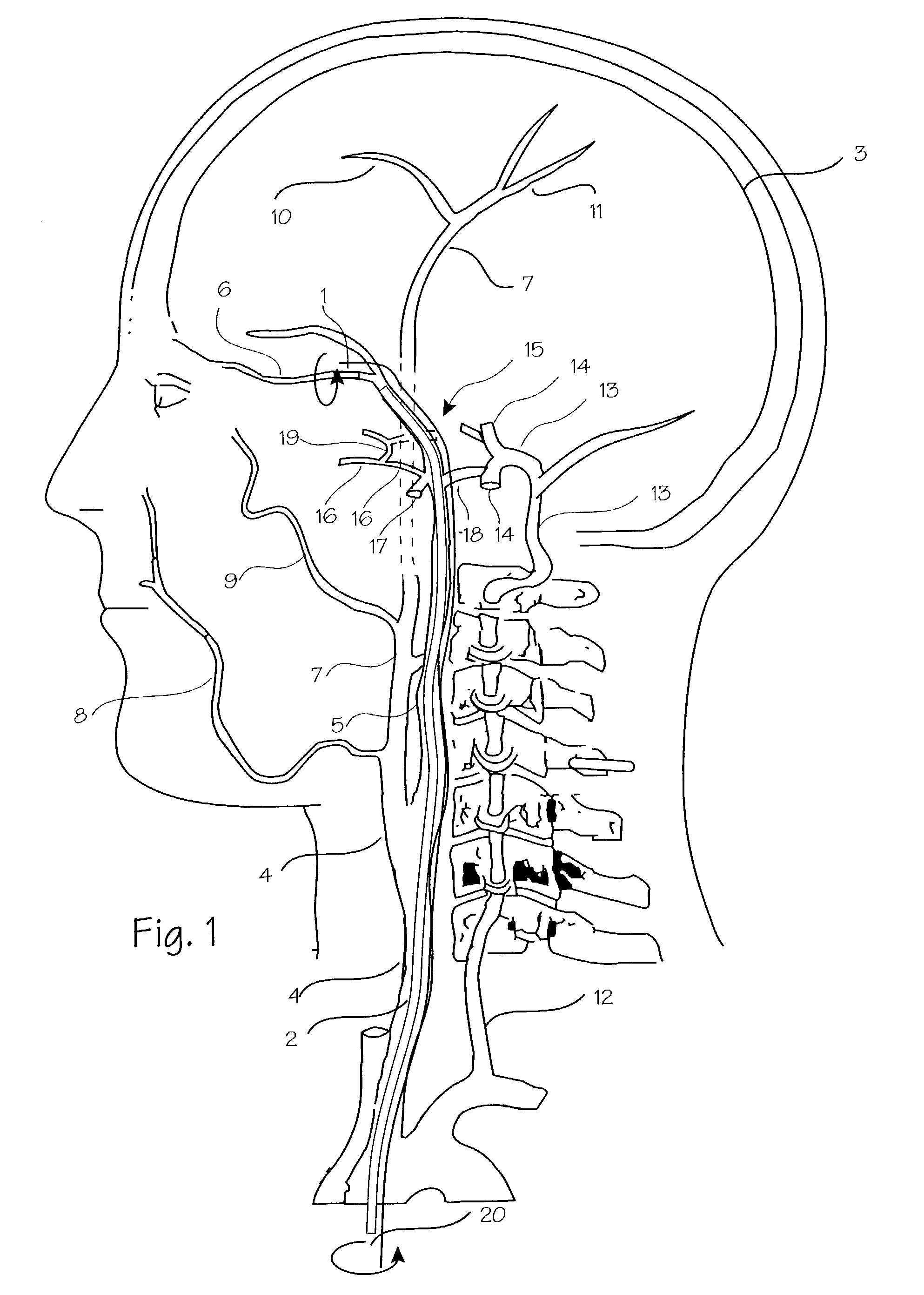
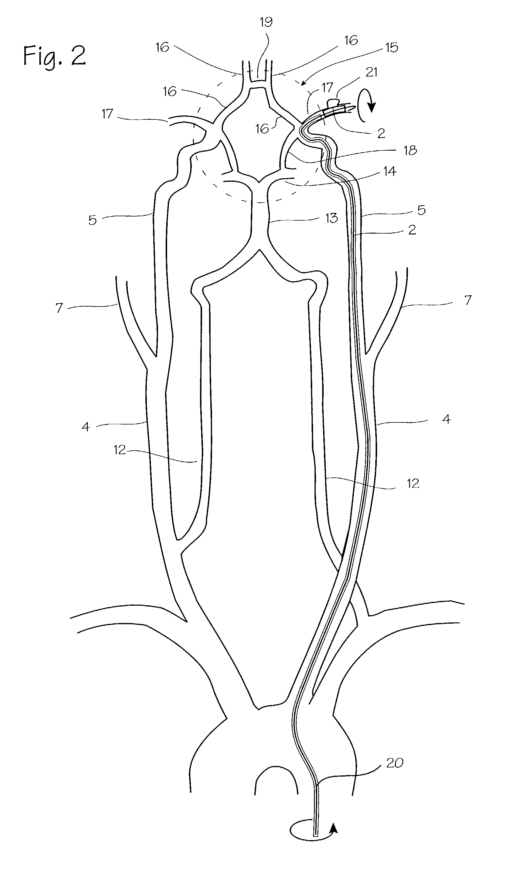
[0023]The stent delivery system is particularly well suited for delivery of stents into very small vessels in the body, such as the blood vessels within the brain. FIGS. 1 and 2 show the vasculature of the brain in sufficient detail to understand the invention. The brain 3 is supplied with blood through the carotid and the vertebral arteries on each side of the neck. The important arteries include the common carotid artery 4 in the neck, which will be the most common access pathway for the stent, the internal carotid 5 which supplies the opthalmic artery 6. The external carotid 7 supplies the maxillary artery 8, the middle meningeal artery 9, and the superficial temporal arteries 10 (frontal) and 11 (parietal). The vertebral artery 12 supplies the basilar artery 13 and the cerebral arteries including the posterior cerebral artery 14 and the circle of Willis indicated generally at 15. Also supplied by the internal carotid artery are the anterior cerebral artery 16 and the middle cere...


PUM


Abstract

An expandable stent has a sheeted material which is expanded from a compacted configuration to an expanded configuration. The sheet is maintained in the compacted configuration at least in part by operation of a dynamic force, and the expansion occurs at least in part by removal of the dynamic force. In preferred embodiments, a biocompatible sheeted material is wrapped around a split reed grasper to produce a compacted configuration, and the split reed grasper is rotated to maintain the compacted configuration during insertion of the stent into a patient. The rotation is continued while the stent is positioned, and then the rotation is stopped or slowed to permit expansion of the sheet.

Description

RELATED PATENTS[0001]This application is a continuation of U.S. patent application Ser. No. 09 / 780,883 filed Feb. 9, 2001, now U.S. Pat. No. 6,406,487, which is a continuation of U.S. patent application Ser. No. 09 / 372,711, filed Aug, 11, 1999, now U.S. Pat. No. 6,187,015, which is a continuation of U.S. patent application Ser. No. 08 / 850,320 filed May 2, 1997, now U.S. Pat. No. 5,957,929.FIELD OF THE INVENTION[0002]This invention relates to expandable stents.BACKGROUND OF THE INVENTION[0003]Stents are endoprostheses which can be deployed into the lumen of an artery or vein, a common bile duct, the urethra or other body passageway. Stents may be employed in such passageways for many purposes, including expansion of a lumen, maintenance of the lumen after expansion, and repair of a damaged intima or wall surrounding a lumen. With respect to arteries, for example, stents may be used as, or in conjunction with, intralumenal grafts in the maintenance of patency of a lumen following angi...

Claims


Application Information

Patent Timeline
Patent Type & Authority Patents(United States)
IPC IPC(8): A61F2/06A61F2/92
CPCA61F2/92A61F2/95A61F2002/9511
Inventor BRENNEMAN, RODNEY A.
Owner EV3
Why Eureka
Try Eureka