Method for producing a monolithic front air deflector

a monolithic, front air deflector technology, applied in the field of air deflectors, can solve the problems of disturbing noise, loss of cooling and aerodynamic characteristics, and the prior art air deflector assembly has proved to be extremely costly to manufacture, so as to improve air deflector function and performance, reduce cost, and improve the effect of air deflector function

Inactive Publication Date: 2006-03-14
GM GLOBAL TECH OPERATIONS LLC
View PDF6 Cites 4 Cited by
  • Summary
  • Abstract
  • Description
  • Claims
  • Application Information

AI Technical Summary

Benefits of technology

[0008]The present invention relates to a unique design utilizing two distinctive plastic compounds in an integral air deflector to enhance air deflector function and performance. The present invention solves the shortcomings of the prior art air deflector assembly by providing a one-piece injection molded dual durometer front center air deflector assembly. The present invention provides many advantages over the prior art including, but not limited to, a substantially lower cost design, and the second portion of the air deflector is a softer durometer material and is barely audible when coming in contact with curbs or driveways. The second portion of the air deflector also has substantially less deflection than the lower portion of the prior art deflector assembly, resulting in better airflow and aerodynamic characteristics. Furthermore, because of the characteristics of the second material, it is anticipated that the present invention will reduce warranty claims substantially.
[0009]The novelty of the present invention is the utilization of two distinctive plastic compounds in an integral one-piece injection molded air deflector to provide rigid mounting to the vehicle, reduced incline and curb scrub noise, and consistent vehicle aerodynamic characteristics.

Problems solved by technology

This type of prior art air deflector assembly, however, has proved to be extremely costly to manufacture.
The prior art assembly also disadvantageously creates a disturbing noise when in contact with curbs or driveways, and there is an excessive deflection of the lower portion at high speeds resulting in loss of cooling and aerodynamic characteristics.
In addition, the prior art assembly has a high warranty cost because of both the high cost and the high frequency of replacing broken air deflectors.

Method used


Image

  • Method for producing a monolithic front air deflector
  • Method for producing a monolithic front air deflector
  • Method for producing a monolithic front air deflector

Examples


Embodiment Construction

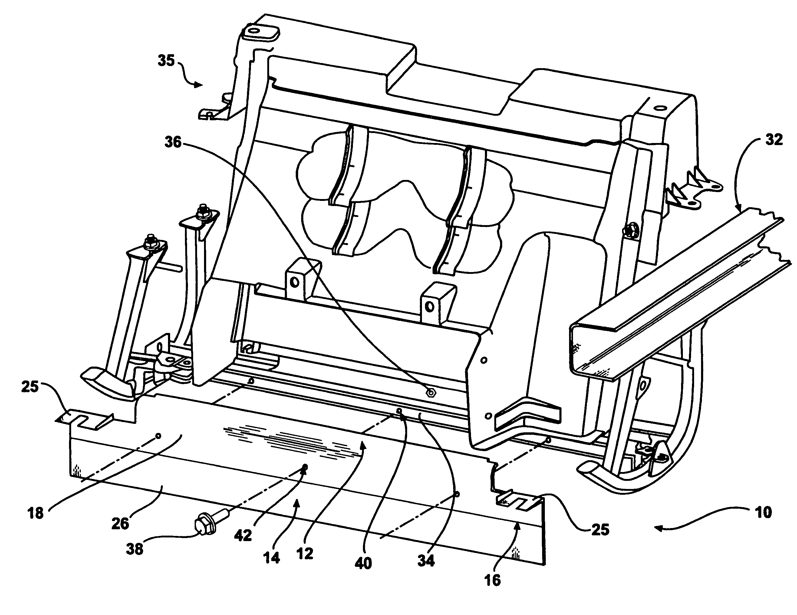
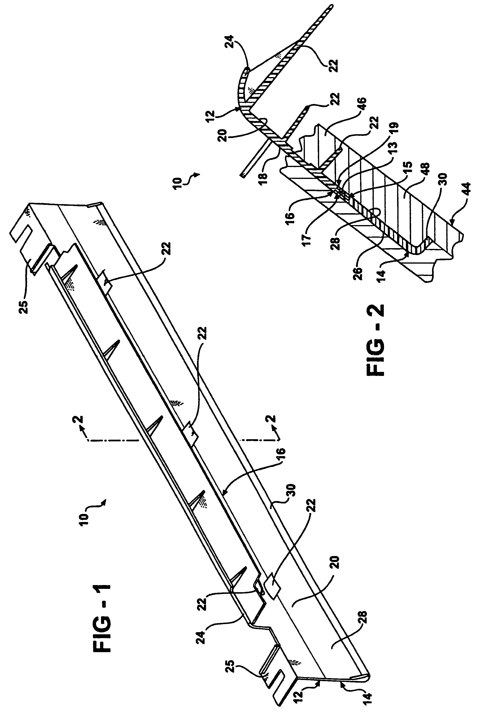
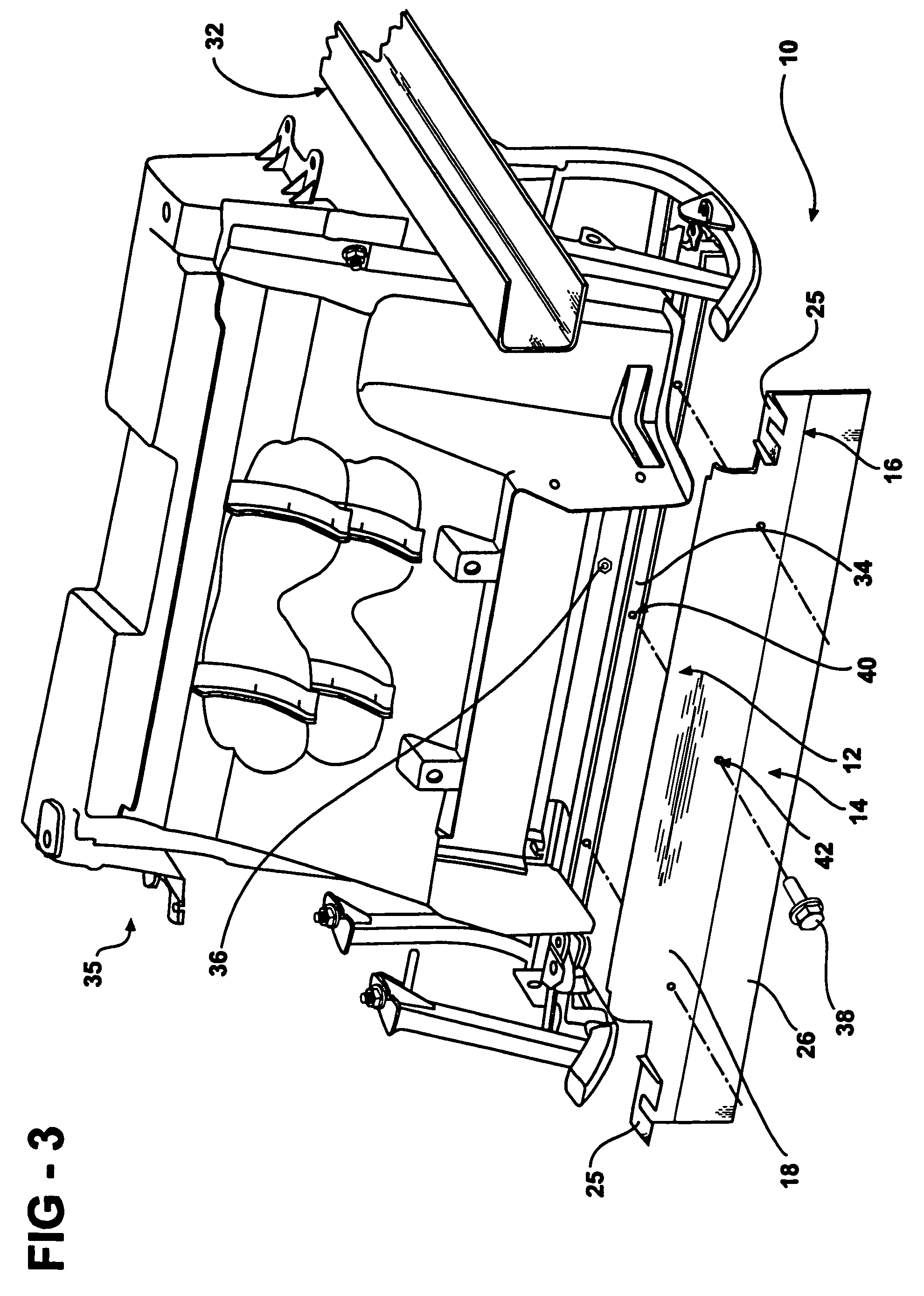
[0015]Referring now to FIGS. 1 and 2, an air deflector according to the present invention is indicated generally at 10. The air deflector 10 includes a first portion 12 and a second portion 14 attached thereto and extending downwardly therefrom to form a generally vertical plane. The first portion 12 is horizontally elongated and is adapted to be attached to a lower surface of a vehicle, outlined in more detail below. The first portion 12 is preferably constructed of a first material having a first durometer value. The first material is preferably a plastic molding material such as polypropylene that has a high durometer value. The high durometer value indicates that the first material has a high hardness property. Preferably the first material is hard and durable enough to be mounted on the lower surface of the vehicle. The second portion 14 is preferably constructed of a second material having a second durometer value. The second material is different than the first material and t...


PUM

PropertyMeasurementUnit
plastic moldingaaaaaaaaaa
molding areaaaaaaaaaaa
dragaaaaaaaaaa

Abstract

An air deflector for attachment to a lower surface of a vehicle includes a first portion and a second portion attached to and extending downwardly from the first portion. The first portion is adapted to be attached to a lower surface of the vehicle and is formed of a first material having a first durometer value. The second portion is formed of a second material different from the first material. The second portion has a second durometer value less than the first durometer value.

Description

RELATED APPLICATION[0001]This application is a division of U.S. Ser. No. 10 / 178,286 filed on Jun. 24, 2002, now U.S. Pat. No. 6,874,842.BACKGROUND OF THE INVENTION[0002]The present invention relates generally to air deflectors for automotive vehicles and, in particular, to an air deflector for attachment to a lower surface of a vehicle and a method for producing the air deflector.[0003]Air dams, or air deflectors, for attachment to surfaces of an automobile body are well known. Air deflectors are typically a rigid panel installed below the front bumper on most modern vehicles to direct airflow thereby reducing drag and lift and increasing heat exchanger cooling. The air deflector diverts air flowing under the vehicle away from suspension and frame components thus reducing the drag of the vehicle. In addition, the pressure behind the air deflector is decreased, which aids the cooling flow across the radiator. The deflector also functions to reduce lift at the front of the vehicle.[00...

Claims


Application Information

Patent Timeline
Patent Type & Authority Patents(United States)
IPC IPC(8): B29C45/16B62D35/00
CPCB62D35/005Y02T10/82
Inventor HOJNA, JOSEPH J
Owner GM GLOBAL TECH OPERATIONS LLC
Why Eureka
Try Eureka