Leadframe-based module DC bus design to reduce module inductance

a leadframe and module technology, applied in the field of direct current buses, can solve the problems of inductive power loss, reduced efficiency, excess heat generation, and reduced switching efficiency, and achieve the effect of reducing inductive poser losses, and reducing switching efficiency

Inactive Publication Date: 2006-03-14
SIEMENS VDO AUTOMOTIVE CORP
View PDF29 Cites 28 Cited by
  • Summary
  • Abstract
  • Description
  • Claims
  • Application Information

AI Technical Summary

Benefits of technology

[0015]The present invention provides a DC bus for use in a power module that is shaped and positioned to minimize the current loops, thus reducing inductive poser losses. The DC bus is also shaped to permit counter-flow of electric currents, thereby canceling magnetic fields and their associated inductances. The DC bus also allows DC current to flow symmetrically and directly to the switches of the module. Symmetric current loops in the module result in more even and efficient motor performance.
[0020]The DC bus and power module disclosed herein provide improved efficiency and more even motor performance through the cancellation of magnetic fields and minimization of current loops. A parallel negative and positive DC bus provides the added benefit of creating capacitance between the plates, which further minimize voltage overshoots produced by the switching process. These and other advantages will become apparent to those of ordinary skill in the art with reference to the detailed description and drawings.

Problems solved by technology

Current flowing through various paths within the module creates inductances, which in turn results in inductive power losses, reduced efficiency, and the excess generation of heat.
When the flow of current changes, as in such a high frequency switching environment, large voltage overshoots often result, further decreasing switching efficiency.
In addition, the DC terminals are commonly attached to one end of the power module, which forces current to travel further to some switches, and thus, for some switching configurations, than for others, resulting in non-uniform current loops.
Current loops that are not uniform result in uneven or inefficient motor performance.

Method used


Image

  • Leadframe-based module DC bus design to reduce module inductance
  • Leadframe-based module DC bus design to reduce module inductance
  • Leadframe-based module DC bus design to reduce module inductance

Examples


Embodiment Construction

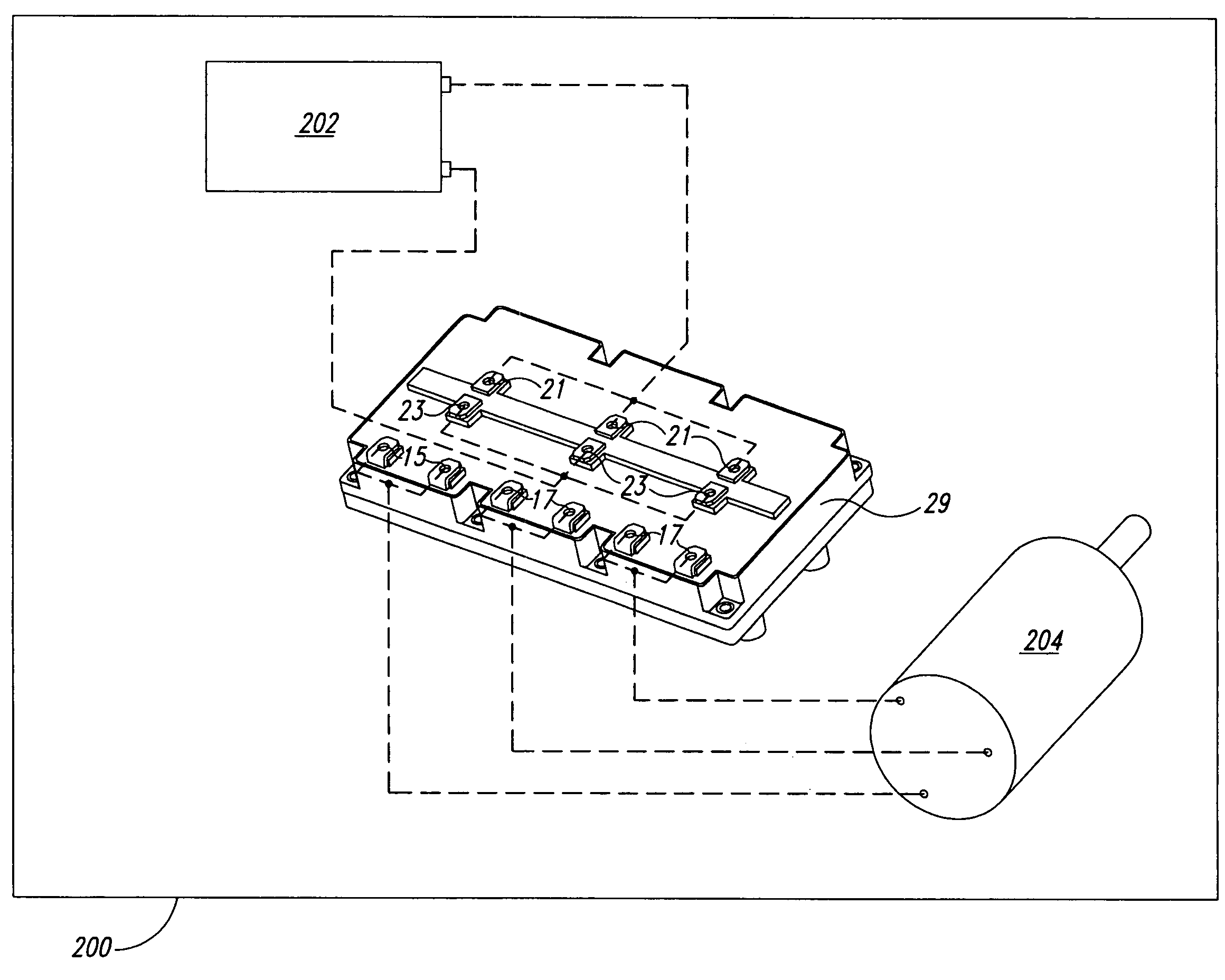
[0036]In accordance with the invention, a DC bus is used in a power module, and the DC bus is shaped and positioned to minimize current loops, voltage overshoots and their associated inductance losses, to provide for symmetric current flow. Reference is made herein to a power module with three phase terminals for use with a three-phase motor and having three bridges, each with two switching pairs. As will be appreciated by one of ordinary skill in the art, the disclosed power module, DC bus, and method for reducing inductance in a power module could be used on a power module with any number of phase terminals and bridges, and having any number of switching pairs. Nonetheless, for ease of description, reference is made to a three-phase power module.

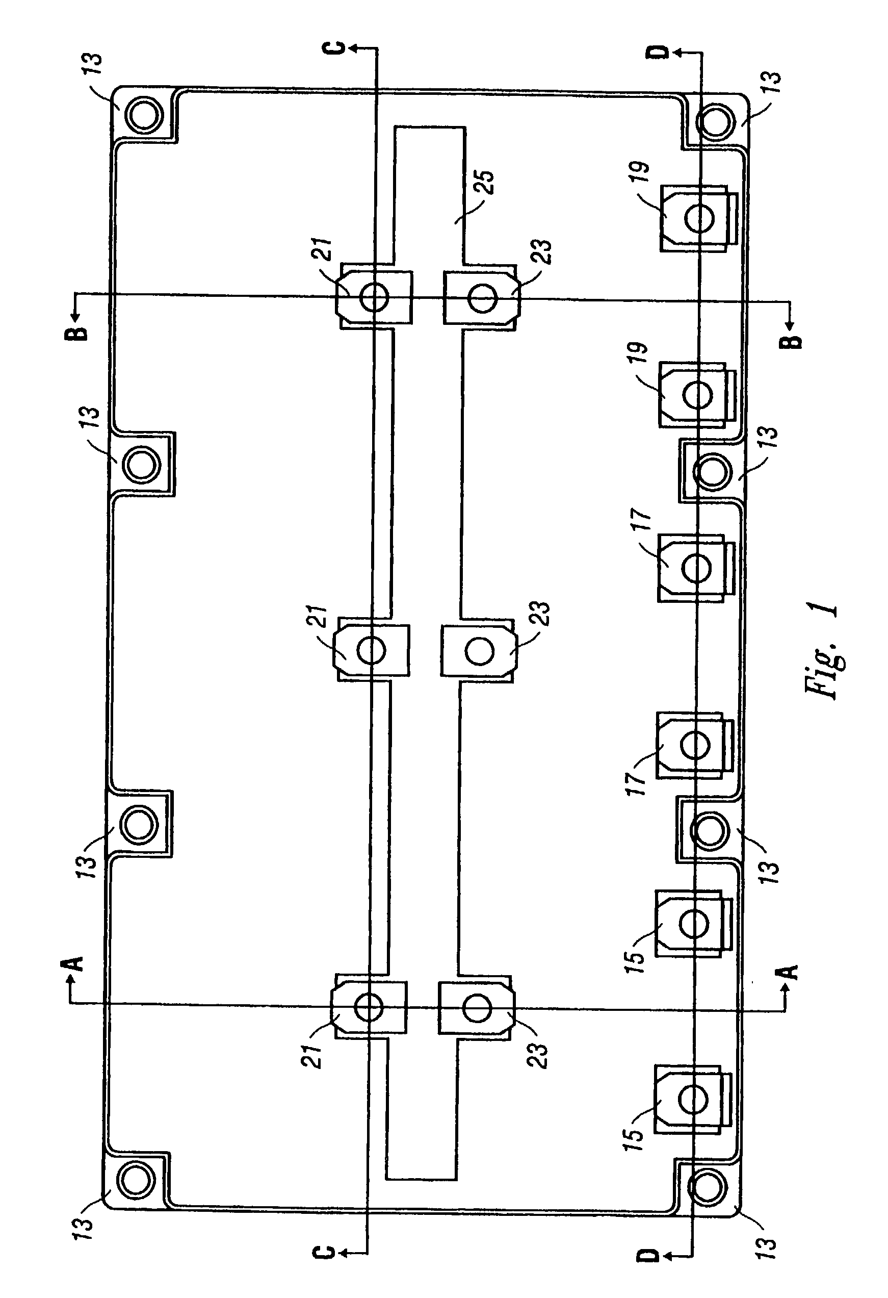
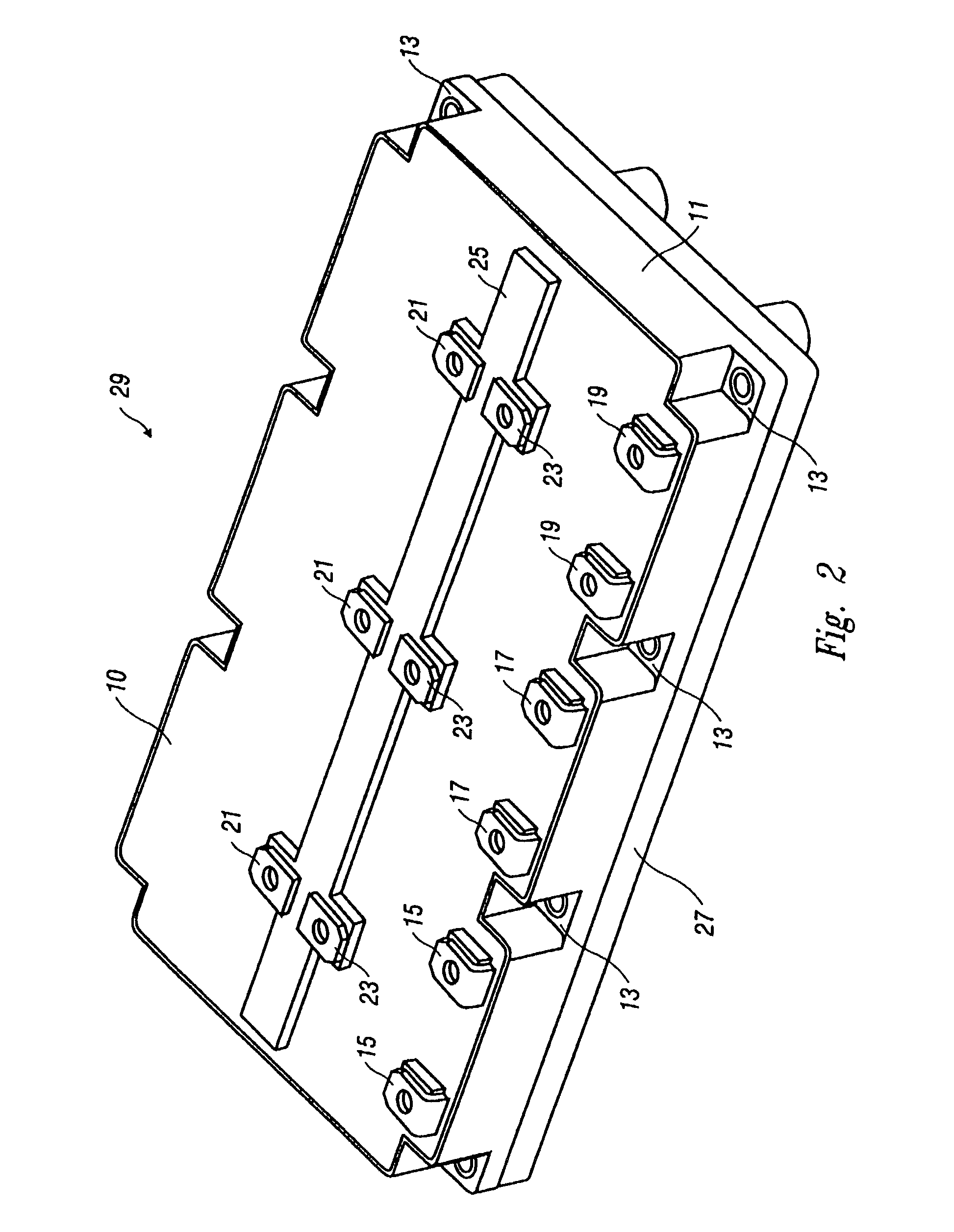
[0037]Referring to FIG. 1, an overhead view of the top of the power module is shown. The module has three positive leads 21 that are connectable to a power source 202 (FIG. 14), such as a battery, and three negative leads 23 that are likew...


PUM

PropertyMeasurementUnit
dielectric strengthaaaaaaaaaa
thicknessaaaaaaaaaa
thicknessaaaaaaaaaa

Abstract

A DC bus for use in a power module has a positive DC conductor bus plate parallel with a negative DC conductor bus plate. One or more positive leads are connected to the positive bus and are connectable to a positive terminal of a power source. One or more negative leads are connected to the negative bus and are connectable to a negative terminal of a power source. The DC bus has one or more positive connections fastenable from the positive bus to the high side of a power module. The DC bus also has one or more negative connections fastenable from the negative bus to the low side of the power module. The positive bus and negative bus permit counter-flow of currents, thereby canceling magnetic fields and their associated inductances, and the positive and negative bus are connectable to the center portion of a power module.

Description

CROSS REFERENCE TO RELATED APPLICATIONS[0001]This patent application incorporates by reference in its entirety, and is a continuation-in-part of, the currently U.S. patent application Ser. No. 09 / 882,708, having a filing date of 15 Jun. 2001, now abandoned, naming Scott Parkhill, Sayeed Ahmed, and Fred Flett as inventors, and claims priority from the foregoing application, and any parents of the foregoing application, under the auspices of 35 U.S.C. § 120.[0002]This patent application incorporates by reference in its entirety, and is a continuation-in-part of, the currently co-pending International Patent Application No. PCT / US01 / 29504, having an International Filing date of 20 Sep. 2001 and a claimed priority date of 20 Sep. 2000, naming Scott Parkhill, Sayeed Ahmed, and Fred Flett as inventors, and claims priority from the foregoing application, and any parents of the foregoing application, under the auspices of 35 U.S.C. § 120 and 35 U.S.C. § 363.[0003]This patent application als...

Claims


Application Information

Patent Timeline
Patent Type & Authority Patents(United States)
IPC IPC(8): H01R9/00H01L23/66H01L25/07H05K1/02H05K1/03
CPCH01L25/072H02M7/003H05K7/1432Y10T29/49002H05K1/0215H05K1/0237H05K1/0306H05K2201/09345H05K2201/10446H05K2201/10636H05K2203/049H01L2223/665Y10T29/49126H01L2924/0002Y10T29/49117Y10T29/49009H01L2924/00Y02P70/50H05K7/14329H05K7/00
Inventor PARKHILL, SCOTTAHMED, SAYEEDFLETT, FRED
Owner SIEMENS VDO AUTOMOTIVE CORP
Why Eureka
Try Eureka