Method for checking the existence of an optical disk using a focusing signal

Inactive Publication Date: 2006-03-14
LG ELECTRONICS INC
View PDF8 Cites 4 Cited by
  • Summary
  • Abstract
  • Description
  • Claims
  • Application Information

AI Technical Summary

Benefits of technology

[0009]It is an object of the present invention to provide a method for checking the existence of an optica

Problems solved by technology

Since the incident laser beam is not reflected, the focus error signal is irregular and contaminated by a significant amount of noise, the level of the focus error signal being much lower than a prescribed reference lev

Method used


Image

  • Method for checking the existence of an optical disk using a focusing signal
  • Method for checking the existence of an optical disk using a focusing signal
  • Method for checking the existence of an optical disk using a focusing signal

Examples


Example

[0024]In order that the invention may be fully understood, preferred embodiments thereof will now be described with reference to the accompanying drawings.

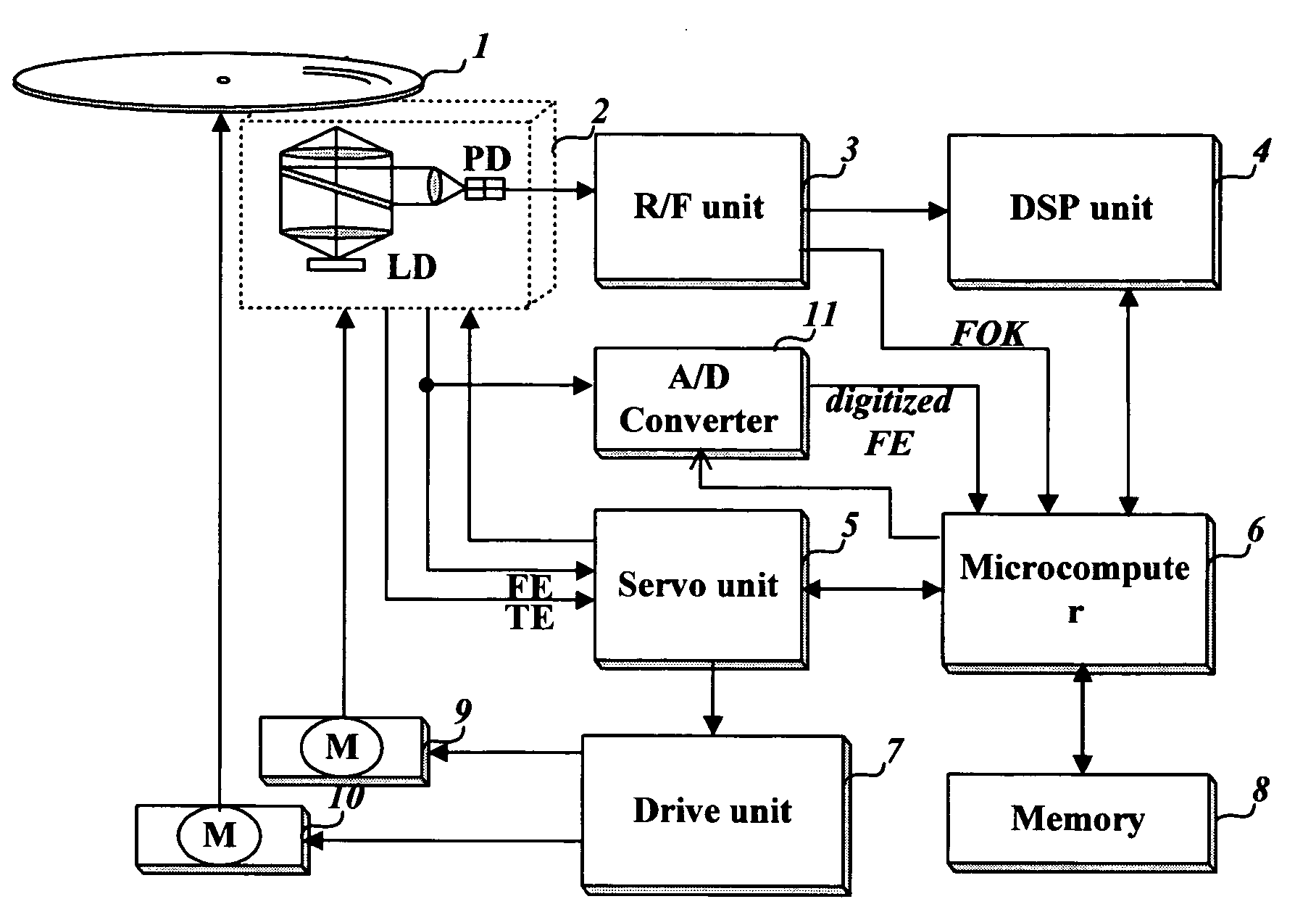
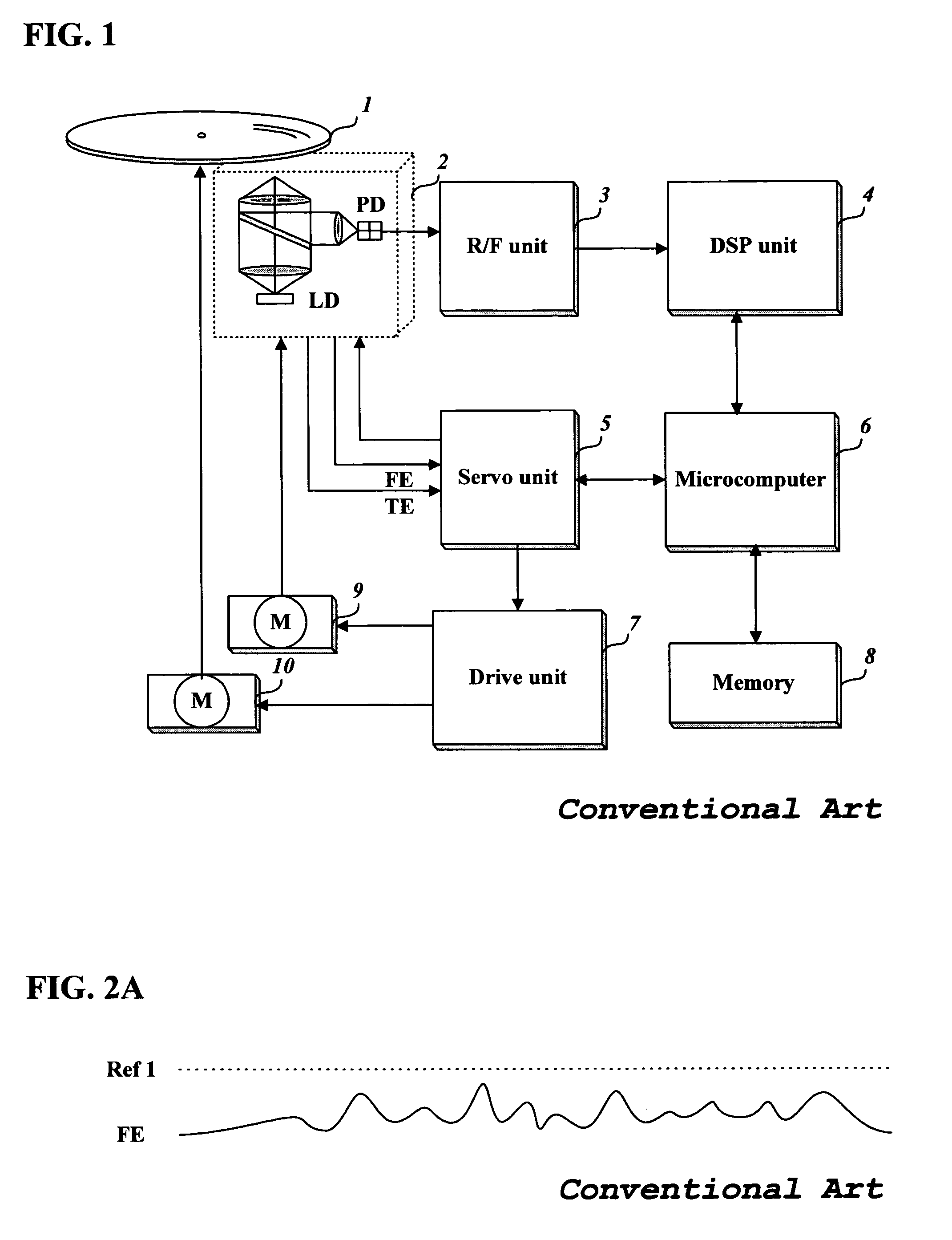
[0025]FIG. 3 shows an optical disk drive embodying the present invention, comprising an optical pickup 2 for reproducing recorded signals from an optical disk 1, a sled motor 9 for moving the optical pickup 2 along the full length of the disk radius, a spindle motor 10 for rotating the optical disk 1, a drive unit 7 for driving the sled motor 9 and the spindle motor 10, an RF unit 3 for equalizing and shaping the RF signal reproduced from the optical disk 1 by the optical pickup 2 and for creating a focus OK (FOK) signal, a servo unit 5 for controlling the optical pickup 2 and drive unit 7 using the rotation speed of the optical disk 1 and focusing and tracking error signals outputted from the optical pickup 2, a digital signal processing unit 4 for retrieving original digital data from the binary data stream outputted by the RF u...


PUM


Abstract

A method for checking the existence of an optical disk using a focusing signal is provided. The method in accordance with the present invention prevents misjudgement of the existence of an optical disk which is caused by noise contained in a focus error signal or by the low reflection ratio of a disk.

Description

BACKGROUND OF THE INVENTION[0001]1. Field of the Invention[0002]The present invention relates to a method for checking the existence of an optical disk, and more specifically, but not by way of limitation, to a method for checking the existence of an optical disk by using the focus error signal or focus OK signal yielded by comparison of a reference level with a beam strength signal.[0003]2. Description of the Related Art[0004]FIG. 1 depicts a general optical disk drive system, comprising an optical pickup 2 for reproducing recorded signals from an optical disk 1, a sled motor 9 for moving the optical pickup 2 along the full length of the disk radius, a spindle motor 10 for rotating the optical disk 1, a drive unit 7 for driving the sled motor 9 and the spindle motor 10, an RF unit 3 for equalizing and shaping the RF signal reproduced from the optical disk 1 by the optical pickup 2, a servo unit 5 for controlling the optical pickup 2 and drive unit 7 using the rotation speed of the ...

Claims


Application Information

Patent Timeline
IPC IPC(8): G11B7/09
CPCG11B19/10
Inventor JEONG, HONG JONA, HYEONG-CHULL
Owner LG ELECTRONICS INC
Why Eureka
Try Eureka