Supercharge Your Innovation With Domain-Expert AI Agents!

Image encoding apparatus and method, program code, and storage medium

Active Publication Date: 2006-03-14
CANON KK
View PDF6 Cites 32 Cited by
  • Summary
  • Abstract
  • Description
  • Claims
  • Application Information

AI Technical Summary

Benefits of technology

[0059]the second scan step of scanning a second region different from the first region at a second

Problems solved by technology

However, the image data size becomes huge with increasing resolution, thus requiring a long transfer time and a large storage size.
However, the aforementioned conventional high-efficiency coding method is not so efficient since it does not consider that different resolutions are required to obtain a high-quality natural image and text / line image upon encoding image data that includes both a natural image and text / line image.
However, the aforementioned conventional high-efficiency coding method is not so efficient, since image data must be temporarily scanned at high resolution upon encoding image data which includes regions having different required resolutions such as an image that includes both a natural image and text / line image.

Method used


Image

  • Image encoding apparatus and method, program code, and storage medium
  • Image encoding apparatus and method, program code, and storage medium
  • Image encoding apparatus and method, program code, and storage medium

Examples


first embodiment

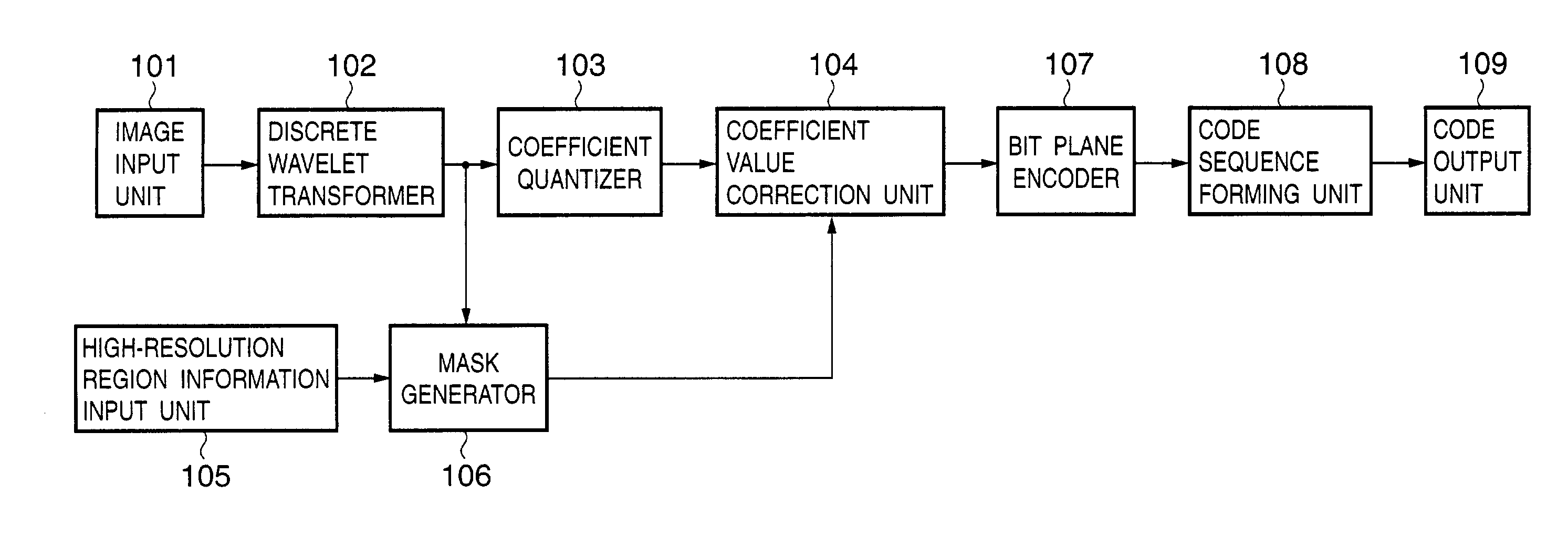
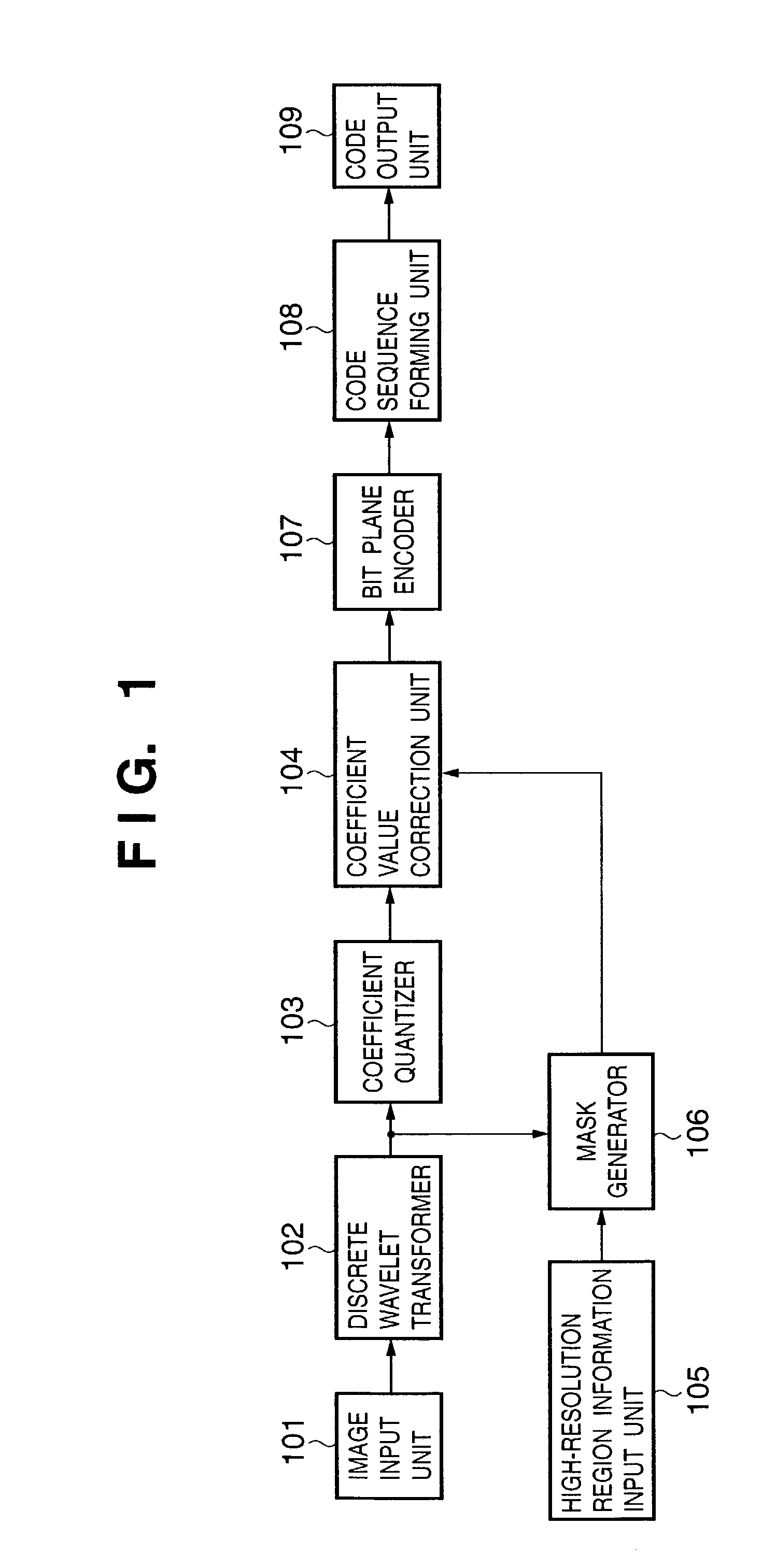
[0082]FIG. 1 shows the functional arrangement of an image encoding apparatus of this embodiment. Referring to FIG. 1, reference numeral101 denotes an image input unit; 102, a discrete wavelet transformer; 103, a coefficient quantizer; 104, a coefficient correction unit; 105, a high-resolution region information input unit; 106, a mask generator; 107, a bit plane encoder; 108, a code sequence forming unit; and 109, a code output unit.

[0083]FIG. 10 shows the basic arrangement of the image encoding apparatus of this embodiment.

[0084]Reference numeral 1001 denotes a CPU which controls the entire image encoding apparatus of this embodiment using programs and data stored in a RAM 1002 and ROM 1003, and executes various encoding processes (to be described later). Reference numeral 1002 denotes a RAM which has an area for temporarily storing programs and data loaded from an external storage device 1004 and storage medium drive 1010, and also has a work area used when the CPU 1001 executes v...

second embodiment

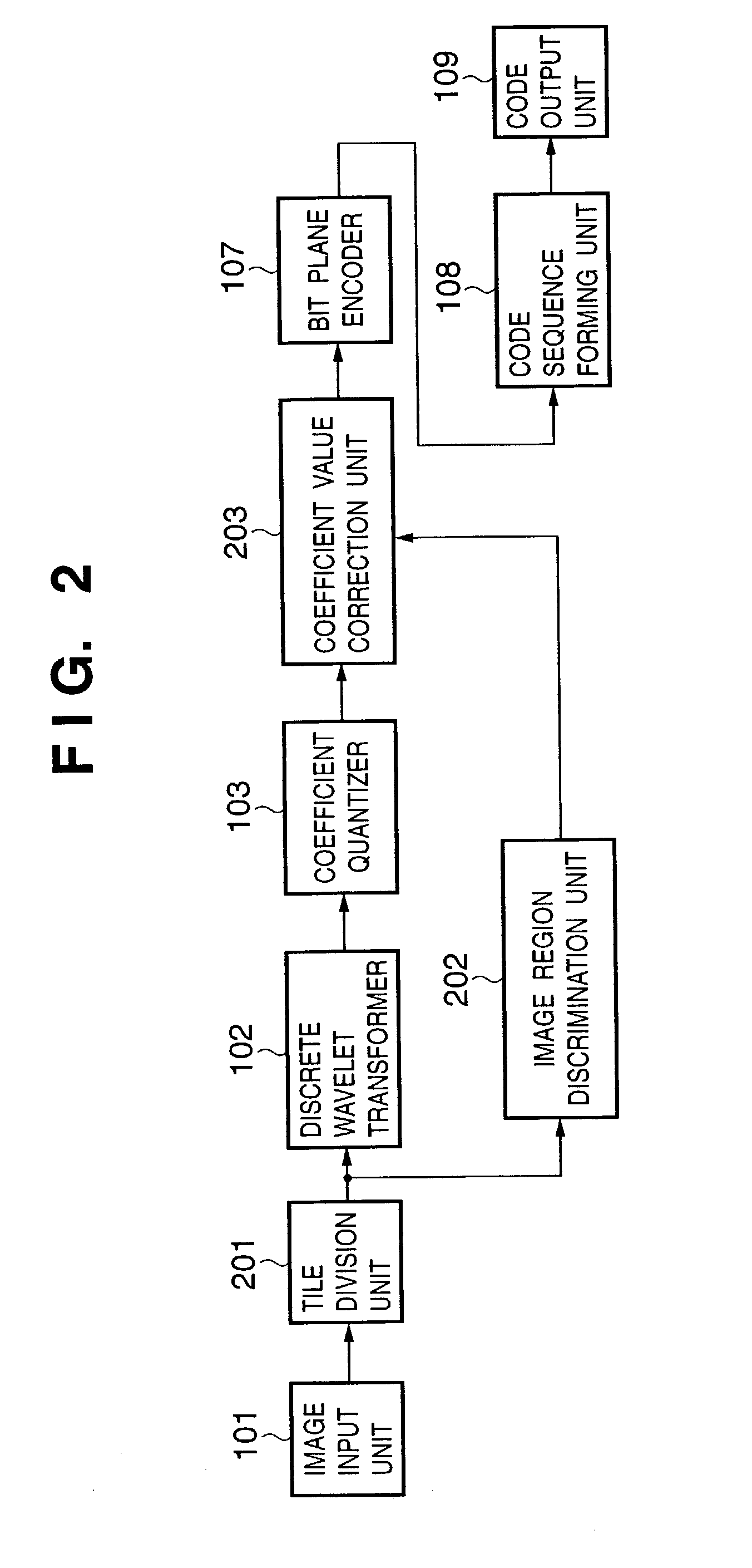
[0111]FIG. 2 shows the functional arrangement of an image encoding apparatus according to this embodiment. The same reference numerals in FIG. 2 denote the same parts as those in FIG. 1, and a description thereof will be omitted. Also, the basic arrangement of the image encoding apparatus of this embodiment is the same as that (FIG. 10) in the first embodiment. Furthermore, a text region in an image is used as a region that requires a high resolution in this embodiment, but the present invention is not limited to such specific region.

[0112]Referring to FIG. 2, reference numeral 201 denotes a tile division unit; 202, an image region discrimination unit; and 203, a coefficient value correction unit.

[0113]In the description of this embodiment, assume that monochrome image data in which the luminance value of one pixel is expressed by 8 bits is to be encoded, as in the first embodiment. However, the present invention is not limited to such specific data, but can be applied to image data...

third embodiment

[0128]FIG. 9 shows the functional arrangement of an image encoding apparatus according to this embodiment. The same reference numerals in FIG. 9 denote the same parts as those in FIGS. 1 and 2, and a description thereof will be omitted. Also, the basic arrangement of the image encoding apparatus of this embodiment is the same as that (FIG. 10) in the first embodiment.

[0129]Referring to FIG. 9, reference numeral 901 denotes an adaptive discrete wavelet transformer. The adaptive discrete wavelet transformer 901 has a function of selecting a filter to be used in subband decomposition in accordance with image region separation information Z.

[0130]In the description of this embodiment, assume that monochrome image data in which the luminance value of one pixel is expressed by 8 bits is to be encoded, as in the first and second embodiments. However, the present invention is not limited to such specific data, but can be applied to image data in which the luminance value is expressed by the...


PUM


Abstract

Image data is decomposed into subbands and quantized by a discrete wavelet transformer (102) and coefficient quantizer (103). On the other hand, a high-resolution region information input unit (105) inputs region designation information H(x, y) that designates a region which requires a high resolution, and a mask generator (106) obtains, based on H(x, y), mask information M(S, x, y) indicating if coefficients of HL2, LH2, and HH2 are generated with reference to pixels of the high-resolution region. A coefficient correction unit (104) corrects the quantized coefficients of respective subbands with reference to M(S, x, y) if subband S is one of HL2, LH2, and HH2, and does not correct if subband S is other than HL2, LH2, and HH2.

Description

FIELD OF THE INVENTION[0001]The present invention relates to an image encoding apparatus and method for encoding image data, a program, and a storage medium.BACKGROUND OF THE INVENTION[0002]In recent years, as the technologies for image input apparatuses such as digital cameras, scanners, and the like have improved, the resolution of image data captured by such input apparatus is increasing. A low-resolution image requires only a small image data size and never disturbs transfer and storage processes. However, the image data size becomes huge with increasing resolution, thus requiring a long transfer time and a large storage size.[0003]Hence, upon transferring or storing an image, it is a common practice to remove redundancy of an image or to reduce the data size by processing an image within a visibly allowable range using high-efficiency coding. A coding scheme that can perfectly reconstruct an original image by decoding is called lossless coding, and a coding scheme which can obt...

Claims


Application Information

Patent Timeline
IPC IPC(8): G06K9/36G06K9/46G06T9/00H04N7/26
CPCH04N19/176H04N19/647H04N19/63H04N19/127H04N19/59H04N19/132H04N19/162H04N19/18H04N19/17H04N19/126
Inventor KAJIWARA, HIROSHI
Owner CANON KK
Features
  • R&D
  • Intellectual Property
  • Life Sciences
  • Materials
  • Tech Scout
  • Unparalleled Data Quality
  • Higher Quality Content
  • 60% Fewer Hallucinations
Learn More