
Method, program, and apparatus for designing a semiconductor device

a semiconductor and device technology, applied in the direction of computer aided design, instrumentation, cad circuit design, etc., can solve the problems of non-uniform pattern density, center of a wiring pattern depressed at chemical mechanical polishing time,

Inactive Publication Date: 2006-03-14
SOCIONEXT INC
View PDF16 Cites 73 Cited by
  • Summary
  • Abstract
  • Description
  • Claims
  • Application Information

AI Technical Summary

Problems solved by technology

With copper wirings, if wiring pattern density is non-uniform, then the center of a wiring pattern will become depressed at chemical mechanical polishing (CMP) time.
Therefore, there may exist an area on a semiconductor chip where a dummy pattern is not inserted, resulting in non-uniform pattern density.

Method used


Image

  • Method, program, and apparatus for designing a semiconductor device
  • Method, program, and apparatus for designing a semiconductor device
  • Method, program, and apparatus for designing a semiconductor device

Examples


Embodiment Construction

[0021]The principles underlying the present invention will now be described first with reference to the drawings.

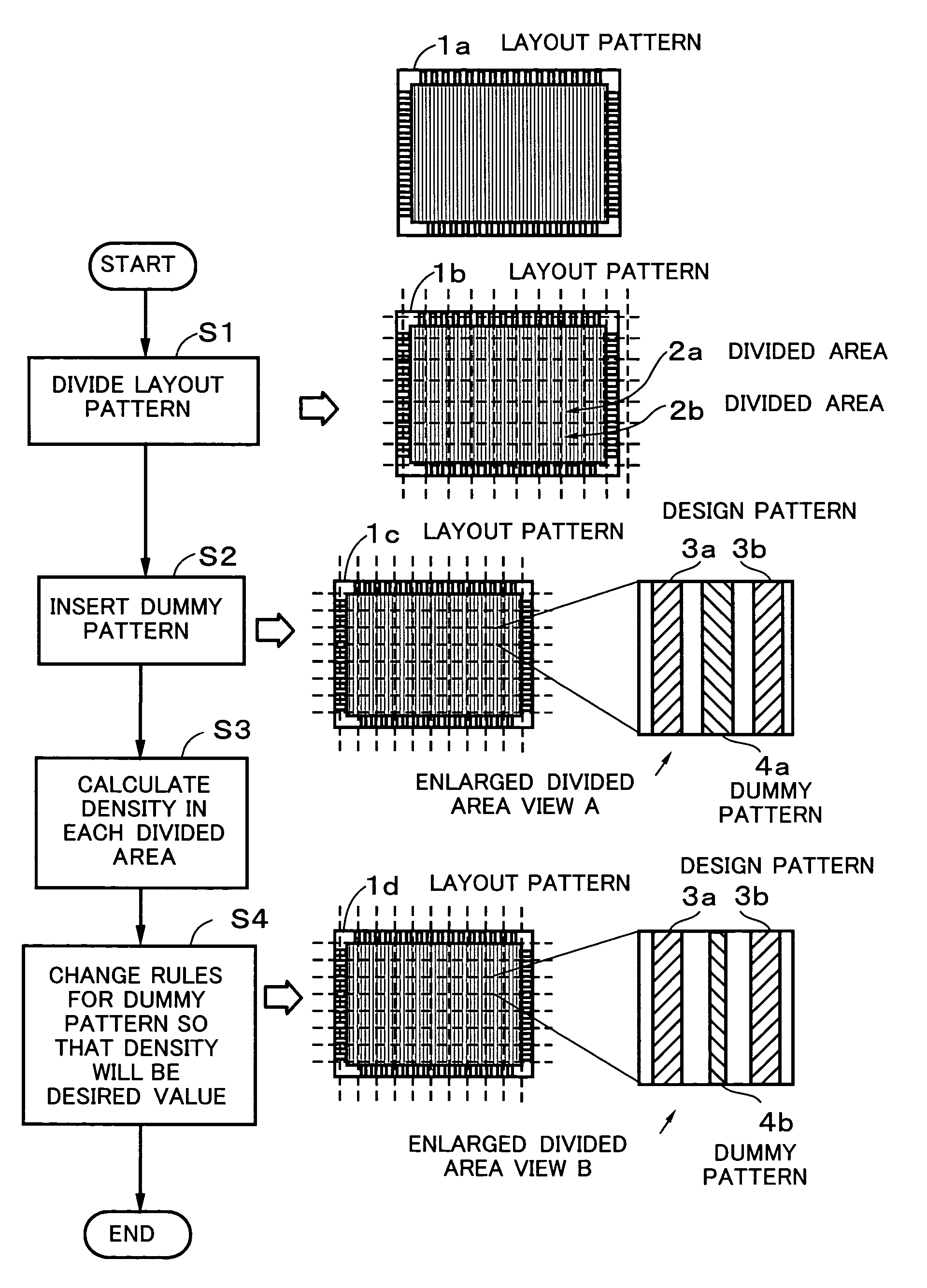
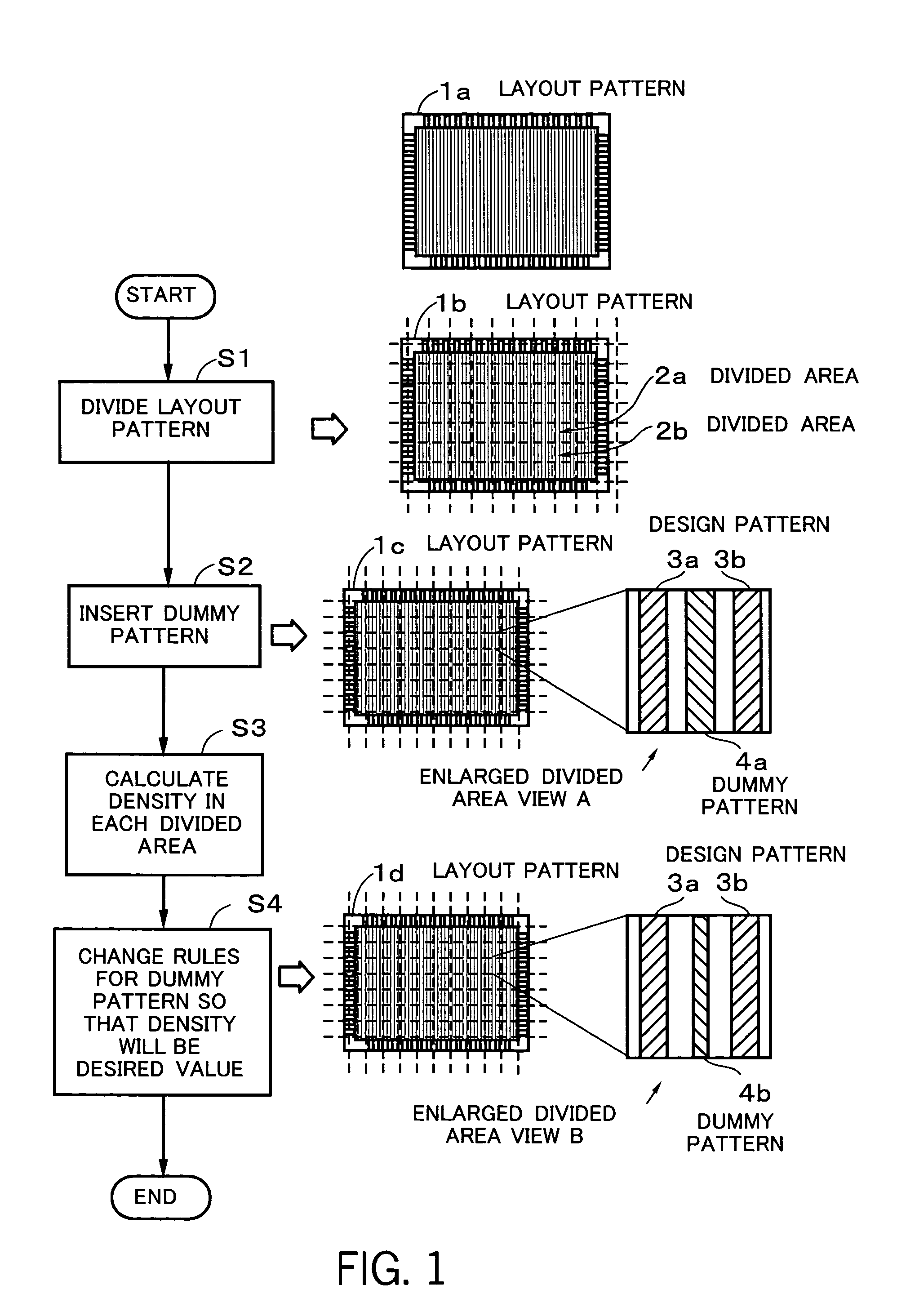
[0022]FIG. 1 is a conceptual view of the present invention. In FIG. 1, the procedure of processes performed by a computer to realize a method for designing a semiconductor device, according to the present invention, is shown. A layout pattern 1a for a layout layer in a semiconductor chip in a semiconductor device to be designed and fabricated is also shown. A layout pattern 1b obtained by dividing the layout pattern 1a into predetermined divided areas is shown. A layout pattern 1c on which a dummy pattern has been inserted between design patterns in a divided area is shown. A layout pattern 1d on which dummy rules for a dummy pattern have been changed is shown. An enlarged divided area view A is an enlarged view of a divided area on the layout pattern 1c. An enlarged divided area view B is an enlarged view of a divided area on the layout pattern 1d.

[0023]A computer perfo...


PUM


Abstract

A method for designing a semiconductor device in which dummy pattern density and design pattern density are equalized on the entire semiconductor chip. A layout pattern for a layout layer in a semiconductor device is divided into divided areas (step S1). A dummy pattern is inserted between design patterns in the divided areas obtained by dividing the layout pattern (step S2). Dummy pattern density and design pattern density in each divided area are calculated (step S3). Pattern rules for a dummy pattern in each divided area are changed so that the dummy pattern density and the design pattern density will be desired values (step S4).

Description

CROSS-REFERENCE TO RELATED APPLICATIONS[0001]This application is based upon and claims the benefits of priority from the prior Japanese Patent Application No. 2002-196865, filed on Jul. 5, 2002, the entire contents of which are incorporated herein by reference.BACKGROUND OF THE INVENTION[0002]1. Field of the Invention[0003]This invention relates to a method, program, and apparatus for designing a semiconductor device and, more particularly, to a method, program, and apparatus for designing a semiconductor device which insert a dummy pattern between design patterns.[0004]2. Description of the Related Art[0005]The technology of inserting a dummy pattern between design patterns is now essential to controlling variations in the flatness of the surface of a chip or the width of design patterns in semiconductor devices caused by non-uniformity of design pattern density. Therefore, design tools for designing semiconductor devices in which a dummy pattern has been inserted have been provide...

Claims


Application Information

Patent Timeline
Patent Type & Authority Patents(United States)
IPC IPC(8): G06F17/50H01L21/768H01L21/82H01L21/822H01L23/528H01L27/04
CPCG06F17/5068H01L23/528H01L21/7684H01L2924/0002G06F30/39H01L2924/00
Inventor OHBA, HISAYOSHIWATANABE, JUN
Owner SOCIONEXT INC
Learn More