Removable collector for liquid cooled exhaust

a collector and liquid cooled technology, applied in the field of exhaust systems, can solve the problems of failure of welded exhaust collectors, difficult welding operations, time-consuming, etc., and achieve the effect of easy repair

Inactive Publication Date: 2006-03-21
COMPX INTERNATIONAL
View PDF9 Cites 18 Cited by
  • Summary
  • Abstract
  • Description
  • Claims
  • Application Information

AI Technical Summary

Benefits of technology

[0016]It is a further object of the present invention to provide provide a removable collector for liquid cooled exhaust, which is less prone to failure.
[0017]Finally, it is another object of the present invention to provide a removable collector for liquid cooled exhaust, which may be more easily repaired, if a failure does occur.

Problems solved by technology

Many of the welding operations are difficult and time consuming to perform.
A major drawback to the welded exhaust collector is failure due to stress corrosion cracking.
Sometimes the header (set of exhaust pipes with exhaust jacket pipe) can be repaired, but most of the time the header cannot be repaired.

Method used


Image

  • Removable collector for liquid cooled exhaust
  • Removable collector for liquid cooled exhaust
  • Removable collector for liquid cooled exhaust

Examples


Embodiment Construction

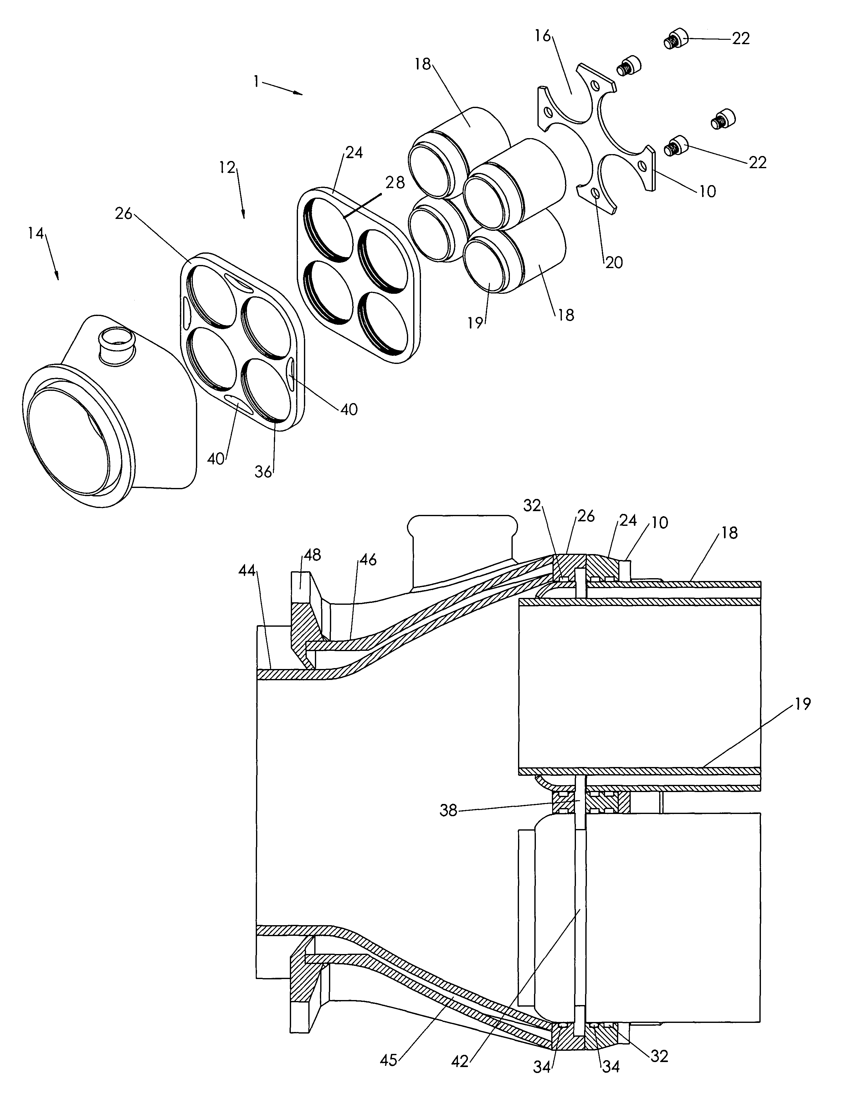
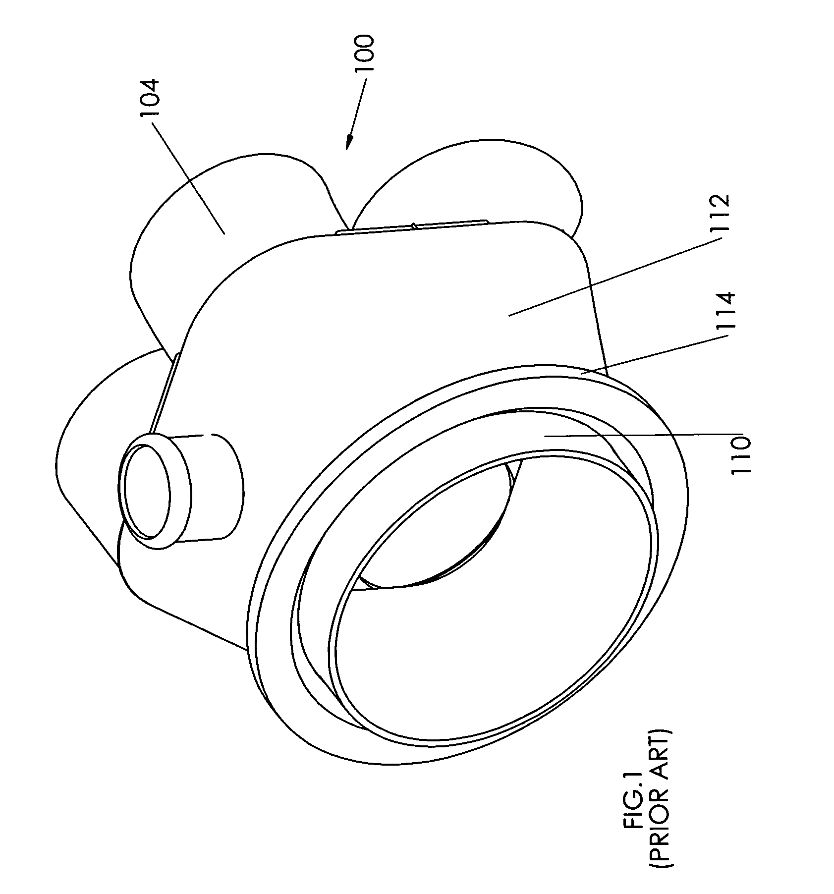
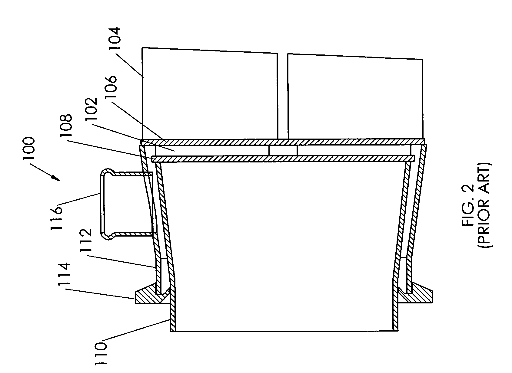
[0034]With reference now to the drawings, and particularly to FIG. 1, there is shown a perspective view of a prior art collector 100. With reference to FIG. 2, the prior art collector 100 includes at least two exhaust pipes 102, at least two exhaust jacket pipes 104, an outer flange 106, an inner flange 108, an inner collector housing 110, an outer collector housing 112 and a clamping flange 114. The outer flange 106 is welded to an end of the at least two exhaust jacket pipes 104 and the inner flange 108 is welded to an end of the at least two exhaust pipes 102. Next, the inner collector housing 110 is welded to the inner flange 108 and the outer collector housing 112 is welded to the outer flange 106. Finally, the clamping flange 114 is welded to a perimeter of the inner collector housing 110 and to an end of the outer collector housing 112.

[0035]Coolant flows between the at least two exhaust pipes 102 and the exhaust jacket pipes 104 into the area between the inner and outer coll...


PUM

PropertyMeasurementUnit
areaaaaaaaaaaa
perimeteraaaaaaaaaa
timeaaaaaaaaaa

Abstract

A removable collector for liquid cooled exhaust includes a retention member, a coolant transfer plate and a collector housing. The retention member fits between at least two exhaust jacket pipes and is attached thereto. Holes are formed through the coolant transfer plate to receive the at least two exhaust jacket pipes and exhaust pipes. The coolant transfer plate is secured to the retention member with fasteners. At least one coolant opening is formed through each exhaust jacket pipe at substantially an end thereof, adjacent a coolant passage cavity in the coolant transfer plate. The collector housing is attached to the coolant transfer plate. Coolant flows between the exhaust pipes and exhaust jacket pipes; through the coolant transfer plate; and through the collector housing. The removable collector for liquid cooled exhaust may be removed from the exhaust pipes by removing the fasteners. The exhaust pipes may be retained in a line.

Description

BACKGROUND OF THE INVENTION[0001]1. Field of the Invention[0002]The present invention relates generally to exhaust systems and more specially to a removable collector for liquid cooled exhaust, which allows a collector to be removed from an end of a set of exhaust pipes without complicated disassembly.[0003]2. Discussion of the Prior Art[0004]It appears, the only prior art that exist for an exhaust collector is a weld-on design. An outer star is welded to an end of a set of exhaust jacket pipes and then an inner star is welded to an end of a set of exhaust pipes. Next, an inner collector housing is welded to the inner star and then an outer collector housing is welded to the outer star. Finally, an end of the outer collector housing is welded to a perimeter of the inner collector housing. Many of the welding operations are difficult and time consuming to perform. A major drawback to the welded exhaust collector is failure due to stress corrosion cracking. The first and second stars ...

Claims


Application Information

Patent Timeline
Patent Type & Authority Patents(United States)
IPC IPC(8): B21D51/16
CPCF01N3/046F28F9/0219F28F2275/085Y10T29/49364F28F2280/02Y10T29/49398Y10T29/49373Y02T10/20Y02T10/12
Inventor ZELINSKI, JOSEPH R.
Owner COMPX INTERNATIONAL
Why Eureka
Try Eureka