
Seat in particular a vehicle seat preferably an aeroplane seat

a vehicle seat and aeroplane seat technology, applied in the field of seats, can solve the problems of affecting the flight of the aircraft, the inability to achieve uniform swivelling motion, and the twisting or torsion of the other seat parts, and achieve the effect of economic tilt adjustment and simple structur

Inactive Publication Date: 2006-09-05
RECARO AIRCRAFT SEATING
View PDF14 Cites 18 Cited by
  • Summary
  • Abstract
  • Description
  • Claims
  • Application Information

AI Technical Summary

Benefits of technology

[0006]Objects of the present invention are to provide an improved seat such that unhindered and uniform tilt adjustment operation of the entire further seat part, such as a backrest or a leg rest, is achieved and such that, in case of a crash, peak loads occurring can be reliably accommodated by the seat structure of the vehicle seat, also in the form of an aircraft passenger seat. Other objects are to provide a seat with an economical tilt adjustment which is of simple structure.
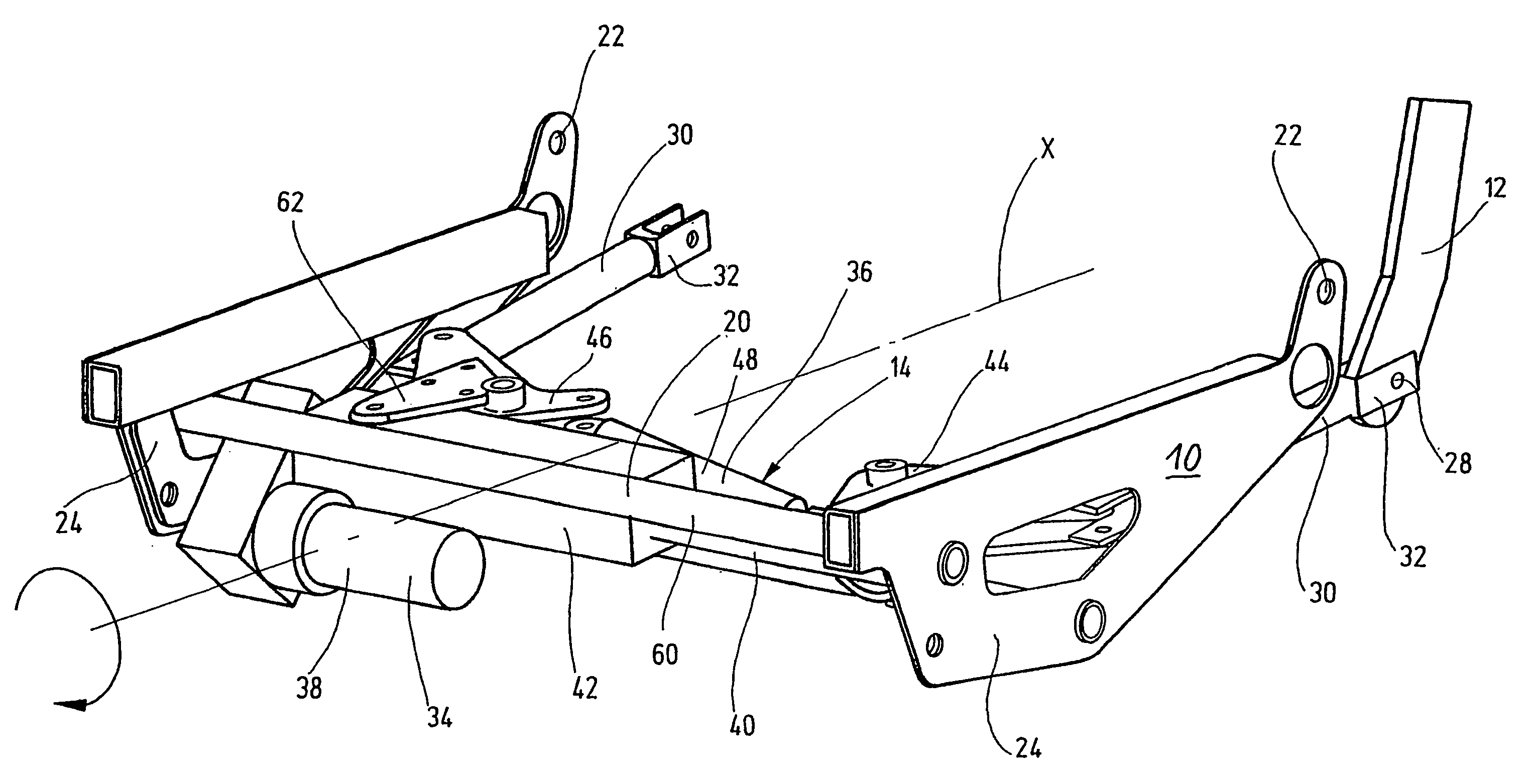
[0008]As a result of the mechanical coupling, the indicated seat parts can be uniformly swivelled over their entire width, and consequently, can be adjusted in tilt around a respective common swivelling axis. Unilateral application of force with its adverse effects is avoided. Since, as a result of the uniform application of force by the two adjustment parts and the mechanical coupling between these two parts, torsion forces within the other seat part and its resulting twisting are avoided. A load on the articulation points which form the swivelling axis is also avoided. By these points, the other seat part, such as the backrest or leg rest, is coupled to the actual seat part of the seat. The mechanical coupling allows relief of the actuating means, for example in the form of a servo-drive so that peak loads in case of a crash can be directly accommodated by the mechanical coupling and can be diverted into the seat frame. The present invention is light in structure making its use in aircraft especially efficient. It is moreover economical to produce. As a result of the mechanical approach, low maintenance costs and few failures can be expected.
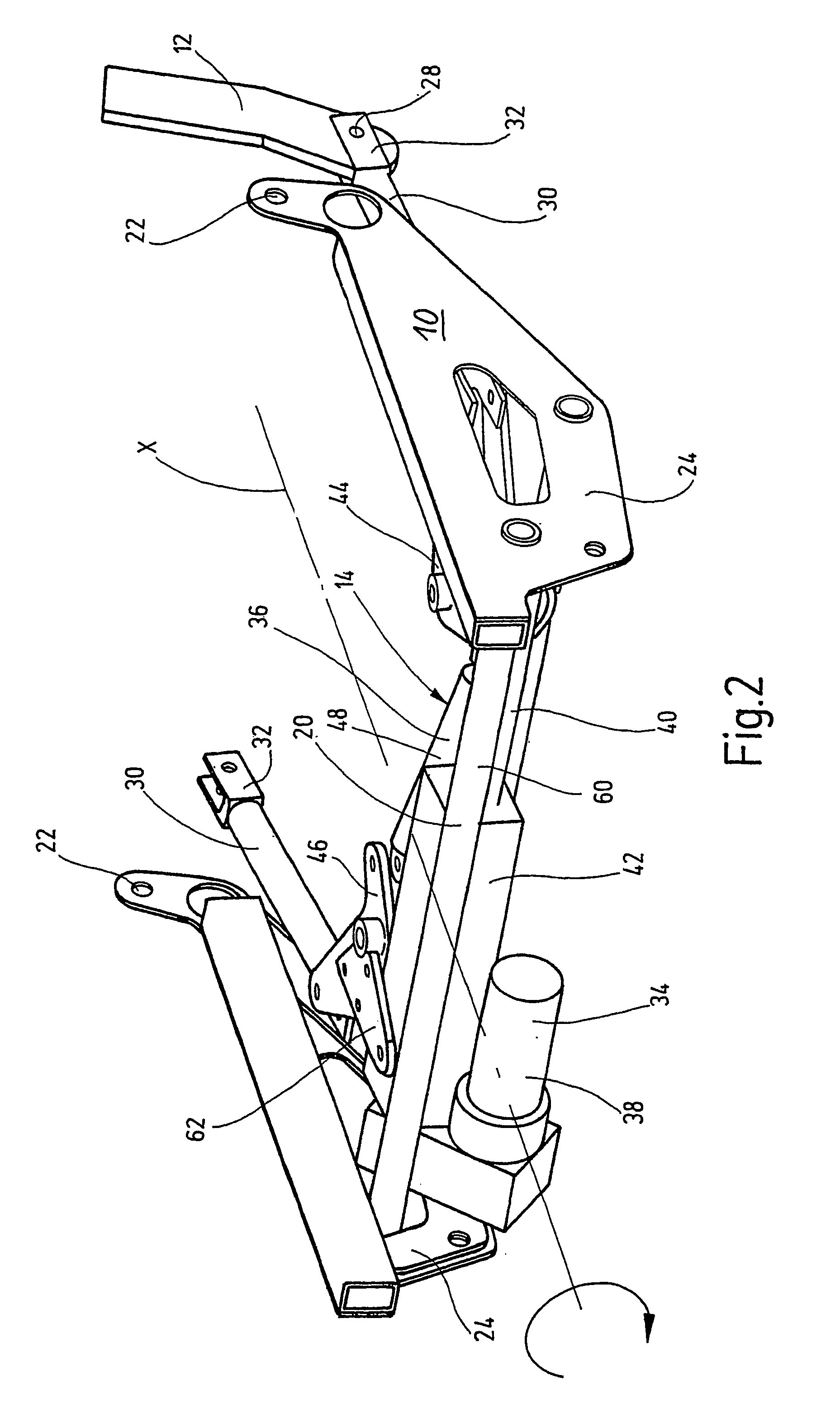
[0009]The actuator means used are economically available commercially and are reliable in operation. In this way, it is possible to convert a small motion of the actuator or servo-drive into a corresponding path of motion for the adjustment part by the indicated angle drive. A uniform and visible tilt adjustment for the other seat part is then achieved. The angle drive allows deflection of the force applied by the actuating part, preferably in the form of an actuating rod of the actuator means in the direction of the adjustment part at almost a right angle. Reliable, dedicated tilt adjustment is possible in spite of the tight installation conditions within the seat frame.
[0010]In one preferred embodiment of the seat of the present invention, the mechanical force coupling includes a rigid component hinged to the angle drives. A load situation initiated in a crash, by the adjustment parts, can consequently be reliably accommodated by a rigid component with relief of the actuator. Preferably, the rigid component extends as a mechanical coupling transversely to the lengthwise direction of the seat to keep the base contour of the seat frame clamped. This arrangement distinctly increases the passive safety for the seat.
[0011]In another preferred embodiment of the seat of the present invention, the actuator housing is rigidly connected to the seat frame for the seat part or is coupled to the other angle drive. In the latter case, actuation of the actuator leads equally to an adjustment motion of the actuator housing and the actuating rod so that with only one actuating process, by way of these two parts, an adjustment path twice as large for the angle drive can be traversed. Preferably, for reliable operation the actuator housing is rigidly held on the seat frame, and driving for the angle drives with the adjustment parts takes place only by the actuating rod and the mechanical coupling.

Problems solved by technology

In all known tilt adjustment means for seat parts, such as a backrest or leg rest, depending on the actuating and tilt adjustment means used at the time, obstacles can arise since generally the actuating means engages only one point of the backrest and / or leg rest.
This single point engagement leads to twisting or torsion of the other seat part to be adjusted in its tilt.
Even with minor twisting or torsion, a uniform swivelling motion cannot be achieved with a good feeling of the body for the seat occupant.
Also, depending on the adjustment structure being used, in case of a crash, unilateral loading of the actuating means, especially in the form of a servo-drive, occurs.
The activating means are often not able to accommodate the forces which suddenly occur.
The known gear approach has a plurality of bevel wheels which fit into one another at a right angle so that the known approach takes up a relatively large amount of construction space on the respective vehicle seat and is accordingly heavy.
Furthermore, the approach based on a plurality of individual components is structurally complex and expensive to produce.
Since synchronous belt drives with their drive wheels and shafts are fundamentally subject to a certain slip behavior, there is no smooth and uniform triggering of the adjustment motion on the two lengthwise sides of the backrest, and obstacles in operation must be expected.
Furthermore, the known and aforementioned approaches have the disadvantage that they are hardly suitable for reliably accommodating the peak loads which occur in the seat base structure in case of a crash, if it is used in the vehicle domain, especially in the aircraft domain.

Method used


Image

  • Seat in particular a vehicle seat preferably an aeroplane seat
  • Seat in particular a vehicle seat preferably an aeroplane seat
  • Seat in particular a vehicle seat preferably an aeroplane seat

Examples


Embodiment Construction

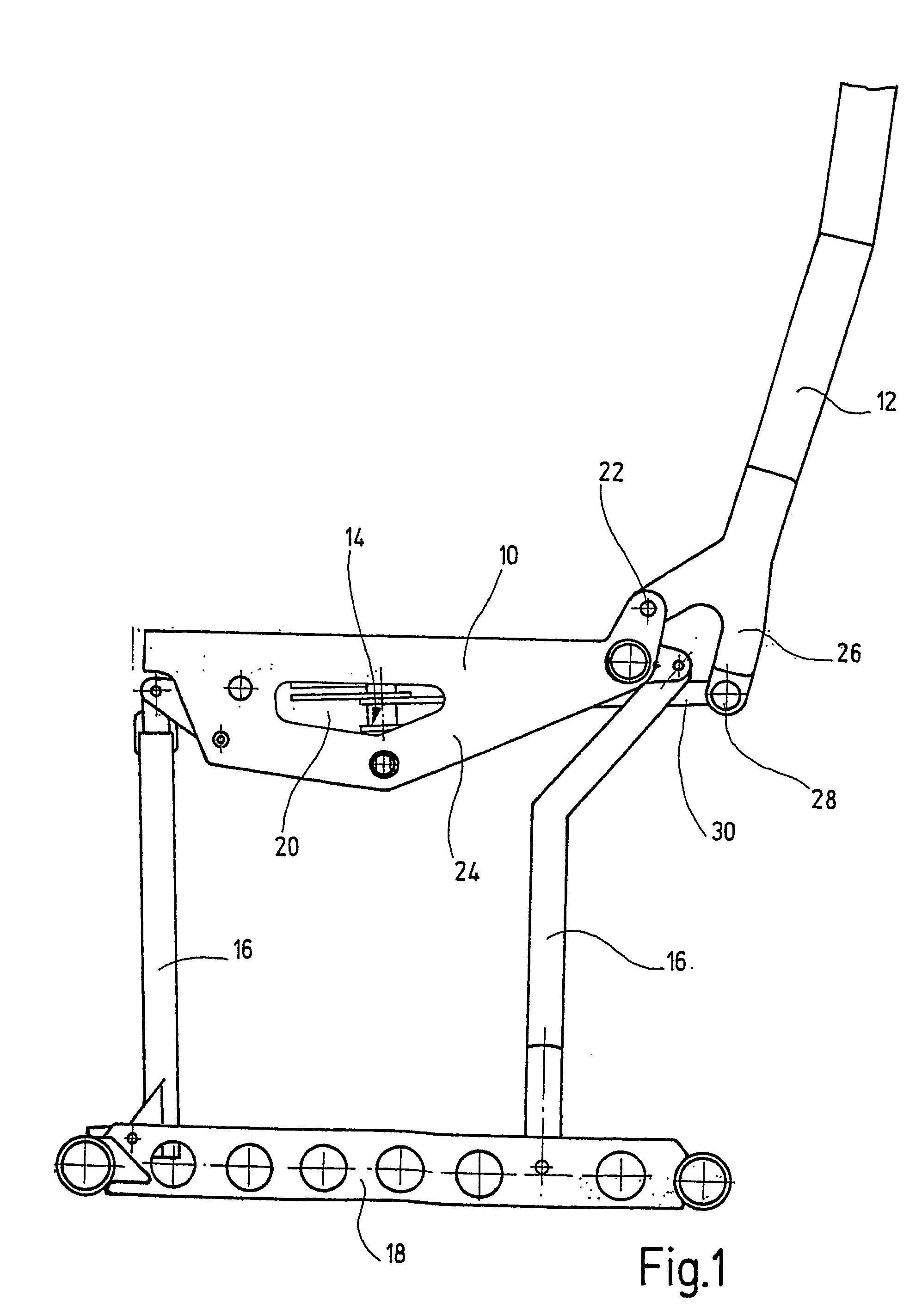
[0021]The embodiment of the vehicle seat of the present invention shown in FIG. 1 is an aircraft passenger seat, as is conventionally used in airliners for passengers. For better illustration, the cushion parts and the leg rest for the seat occupant are omitted. The aircraft passenger seat has a first seat part 10 and another or second seat part 12 with adjustable tilt in the form of a backrest. The backrest is positioned to be able to swivel an actuating means 14 in its tilt relative to the essentially horizontally extending first seat part 10. The first seat part 10 can in turn be mounted on the vehicle floor by stationary legs 16 using seat rails 18. As illustrated, especially by FIGS. 2 and 3, the pertinent seat structure shown in FIG. 1 is essentially doubled in a successive arrangement, and in this way, constitutes a seat frame 20. The pertinent structure is conventional in aircraft passenger seats and is not described in detail.

[0022]For tilt adjustment, the backrest 12 with ...


PUM


Abstract

A seat includes a first seat piece (10) and a further seat piece (12), which may be adjusted for inclination by a controllable operating device (14). The operating device (14) engages the further seat piece (12) by at least two adjusters (30), which are moved by a common drive mechanism (34) with a mechanical coupling (36) between the adjusters (30), for an effectively uniform motion. A uniform inclination adjustment of the further seat piece, such as backrest and / or leg rest is achieved. The drive includes an actuator device with a longitudinally displaceable operating piece (40), engaged with a rocker (44), connected to an adjuster piece (30) and operating the mechanical coupling (36), with a further rocker (46), for the other adjuster (30).

Description

FIELD OF THE INVENTION[0001]The present invention relates to a seat, in particular a vehicle seat, preferably an aeroplane seat, with a first seat part, and with another seat part which can be adjusted in tilt by a triggerable actuating means. The actuating means engages the other seat part with at least two adjustment parts which can be moved by a common drive. Uniform movement of the adjustment parts in this respect causes mechanical coupling between them.BACKGROUND OF THE INVENTION[0002]A pertinent aircraft passenger seat, described in DE 199 44 620, has individual seat components, including a leg rest and a backrest. These seat components can be moved by actuating means which can be triggered by a hand-operated actuating means for adjusting the seat to the requirements of the seat occupant. Hand levers for the seat parts are modeled to the contours of these seat parts as an element of the actuating means, and are combined in one operating part for adjusting the aircraft passenge...

Claims


Application Information

Patent Timeline
IPC IPC(8): B60N2/22B60N2/02B60N2/23B64D11/06
CPCB60N2/0224B60N2/0232B60N2/0252B60N2/23B64D11/0643B64D11/0696B64D11/064B64D11/0619B64D11/06395B64D11/06B60N2/02246
Inventor WAGNER, WOLFGANGBAUMANN, JURGEN
Owner RECARO AIRCRAFT SEATING
Learn More