Unit set for robot

a robot and unit technology, applied in the field of unit sets for robots, to achieve the effect of reducing size, increasing quality and diversity, and reducing siz

Inactive Publication Date: 2006-03-21
BANDAI CO LTD
View PDF20 Cites 66 Cited by
  • Summary
  • Abstract
  • Description
  • Claims
  • Application Information

AI Technical Summary

Benefits of technology

[0006]In light of the above problems of the background art with regard to the reduction in size in the increased quality and diversity, it is an object of the present invention to provide a unit set for a robot, wherein: a surface profile of a joint unit for a robot is arranged so as to be a dice-like cube or a uniaxial cylindrical body or an orthogonal dual-axis cylinder-like cube in which a joint means separation distance is uniform; a joint means is arranged so as to comprise N positioning projections disposed at equally spaced angles around an axis and N connecting screw holes disposed at positions rotated therefrom by 360° / 2N around the axis; a rotating driving means such as motors are arranged so as to be plural ones which cooperatively perform driving motions via a single intermediate gear; a single stay for a robot is arranged so as to comprise, on both ends thereof, the N fitting holes capable of fitting to the N positioning projections on the joint means at each rotational position of 360° / 2N around the axis, as a joint receiving means; a double stay for a robot is arranged so as to comprise, on both ends thereof, an axially supporting receiving means such as axially supporting holes or the like rotatably fitting to an axially supporting means such as axially supporting pins disposed opposite to the joint means on a casing surface of the joint unit; an L-shaped stay for a robot is arranged so as to comprise the joint receiving means on both ends thereof; a dual-axial joint power transmission unit for a robot is arranged so as to convert and transmit the rotations of an input joint rotating shaft connected to the joint means of the joint unit for a robot fixed to the casing into rotations of an output joint rotating shaft disposed so as to put a joint unit separation distance from the input joint rotating shaft; a zero-degree joint power transmission unit for a robot is arranged so as to convert and transmit the rotations of the joint unit for a robot rotating by itself relatively as to an input joint fixed shaft fixed to the casing into the rotations of the output joint rotating shaft disposed so as to put the joint unit separation distance from the input joint fixed shaft; and a unit set for a robot is configured so as to include the joint unit for a robot, the single stay for a robot, the double stay for a robot, the L-shaped stay for a robot, the dual-axis joint power transmission unit for a robot, and the zero-degree joint power transmission unit for a robot; thereby implementing various types of robot structures ensuring a wide variety of functions and a wide variety of configurations, advantageous is the reduction in size due to the installation at high densities, with a high degree of convenience in the assembly construction work, and advantageous in ensuring natural rotational moving functions shared with those of living creatures.

Problems solved by technology

With regard to joint units for robots and robot structures constructed by assembling such joint units on the basis of such background arts, there has been the problem of insufficiencies in the point of the reduction in size by high-density installation of the components in the unit itself, in the point of the increased quality from the aspect of ensuring convenience in the assembling work and ensuring natural rotational motions, and in the point of the diversity of expressible configurations for a robot.

Method used


Image

  • Unit set for robot
  • Unit set for robot
  • Unit set for robot

Examples


Embodiment Construction

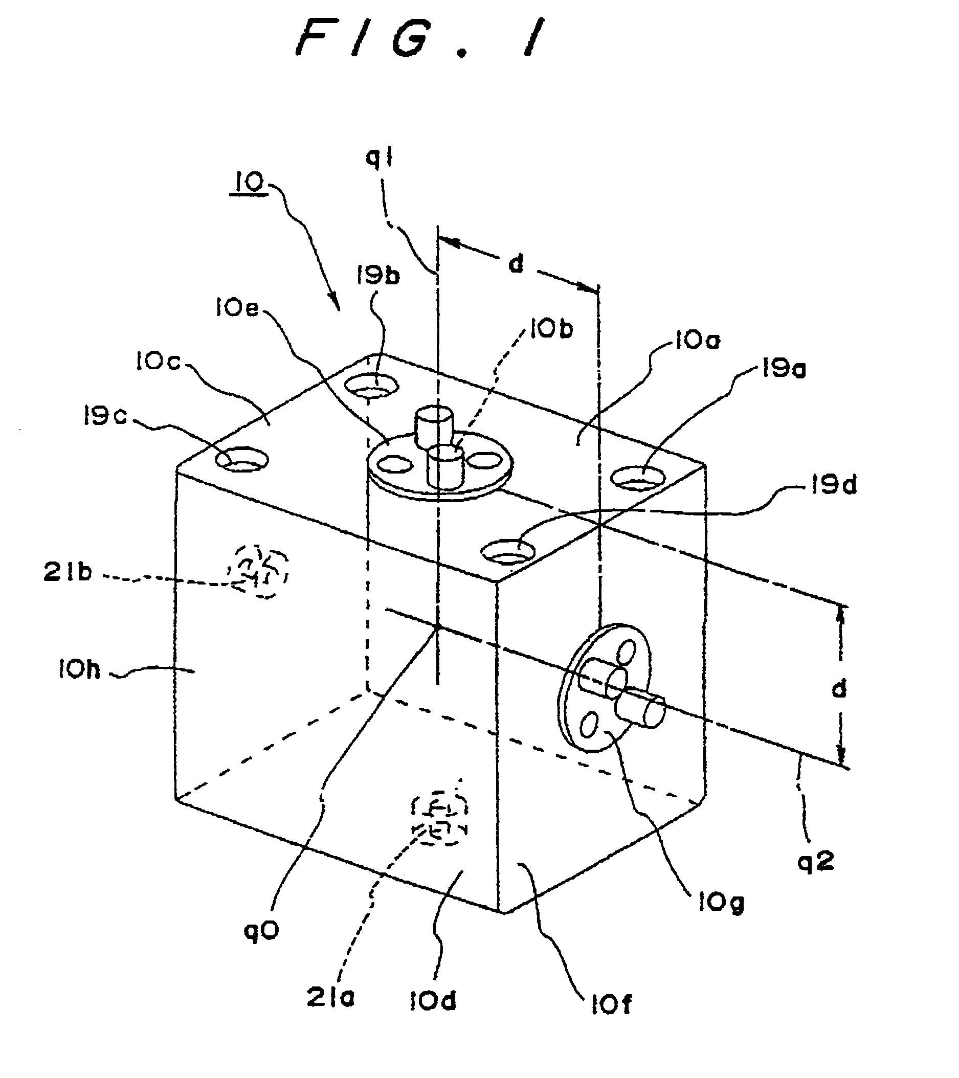
[0065]A best mode for carrying out a first aspect of the present invention will be described with reference to FIGS. 1, 2, 3(A), 3(B), 4, 5(A), 5(B), 6(A) and 6(B). As shown in FIG. 1, an output rotating shaft 10b is rotationally driven with rotations of a driving rotating shaft of rotating driving means such as a motor or the like encapsulated within a cubic joint casing 10a having a die-like external appearance and fixed thereto. The aforesaid rotations are transmitted via reducing means such as a gear train or the like. The output rotating shaft 10b has as a center axis q1 thereof, an axis of which is orthogonal to a pair of opposing surfaces 10c and 10d at an arbitrary position on a surface profile of the joint casing 10a, passing through one surface 10c of the casing and extending outwards, and an output rotating shaft is provided with a rotating joint means 10e for relatively rotating as to the surface 10c of the joint casing 10a by rotating as one body therewith.

[0066]A fixed...


PUM


Abstract

A unit for constructing a robot with units, wherein a joint unit comprises joint means and is organized in a joint casing having a surface profile of a dice-like cube, or a uniaxial cylindrical body, or an orthogonal dual-axis cylinder-like cubic with a uniform joint means separation distance. The joint means comprises N positioning projections disposed about the center axis thereof at equal intervals and equal angles and N connecting screw holes respectively disposed at positions rotated from these projections by 360° / 2N about the center axis thereof. Also, a zero-degree joint power transmission unit converts and transmits the rotations of the joint unit rotated, by itself, relative to an input joint fixed shaft fixed to the joint casing, to the rotations of an output rotating shaft disposed a joint unit separation distance away thereform.

Description

BACKGROUND[0001]The present invention relates to a unit set for a robot, consisting of multiple types of units which are freely connected one with another to configure a robot, and particularly relates to a unit set for a robot including robot joint units for realizing the functions of joints by ensuring rotational driving of a rotating joint means facing outwards by means of a rotation driving means such as a built-in motor or the like, thereby rotationally driving other external components detachably connected to the rotating joint means.[0002]Various types of such robot joint units have already been realized, with one typical example being disclosed in Japanese Examined Patent Application Publication No. 63-50155. According to this typical example, as shown in FIG. 20, a joint unit 1 is configured with an output rotating shaft 1c of a motor 1b equipped with a reducing device and assembled in an inner casing 1a, being connected to the inner face of an outer casing 1e via a couplin...

Claims


Application Information

Patent Timeline
Patent Type & Authority Patents(United States)
IPC IPC(8): B25J17/00F16L29/00A61J1/10A61M39/00A61M39/02A61M39/04B25J9/08B25J9/10B25J17/02B25J19/00B65D51/00F16K24/00F16L37/40
CPCB25J9/08B25J9/102B25J17/025Y10T74/20335Y10T74/20317Y10T74/20329
Inventor KAZAMI, KEIICHI
Owner BANDAI CO LTD
Why Eureka
Try Eureka