Variable cylinder capacity engine

a technology of variable cylinder capacity and mechanical transmission device, which is applied in the direction of connecting rods, mechanical apparatus, crossheads, etc., can solve the problems of vertical compactness and cylinder seized, and achieve the effect of reducing the vertical bulk of the mechanical transmission device and improving the guidance and fixing of the piston

Inactive Publication Date: 2006-03-21
MCE 5 DEV 72 PART INTEREST
View PDF8 Cites 26 Cited by
  • Summary
  • Abstract
  • Description
  • Claims
  • Application Information

AI Technical Summary

Benefits of technology

[0004]The mechanical transmission device according to the present invention proposes solutions for lightening the racks and the toothed wheel while at the same t

Problems solved by technology

This patent also solved problems related to risks of the piston becoming se

Method used


Image

  • Variable cylinder capacity engine
  • Variable cylinder capacity engine
  • Variable cylinder capacity engine

Examples


Embodiment Construction

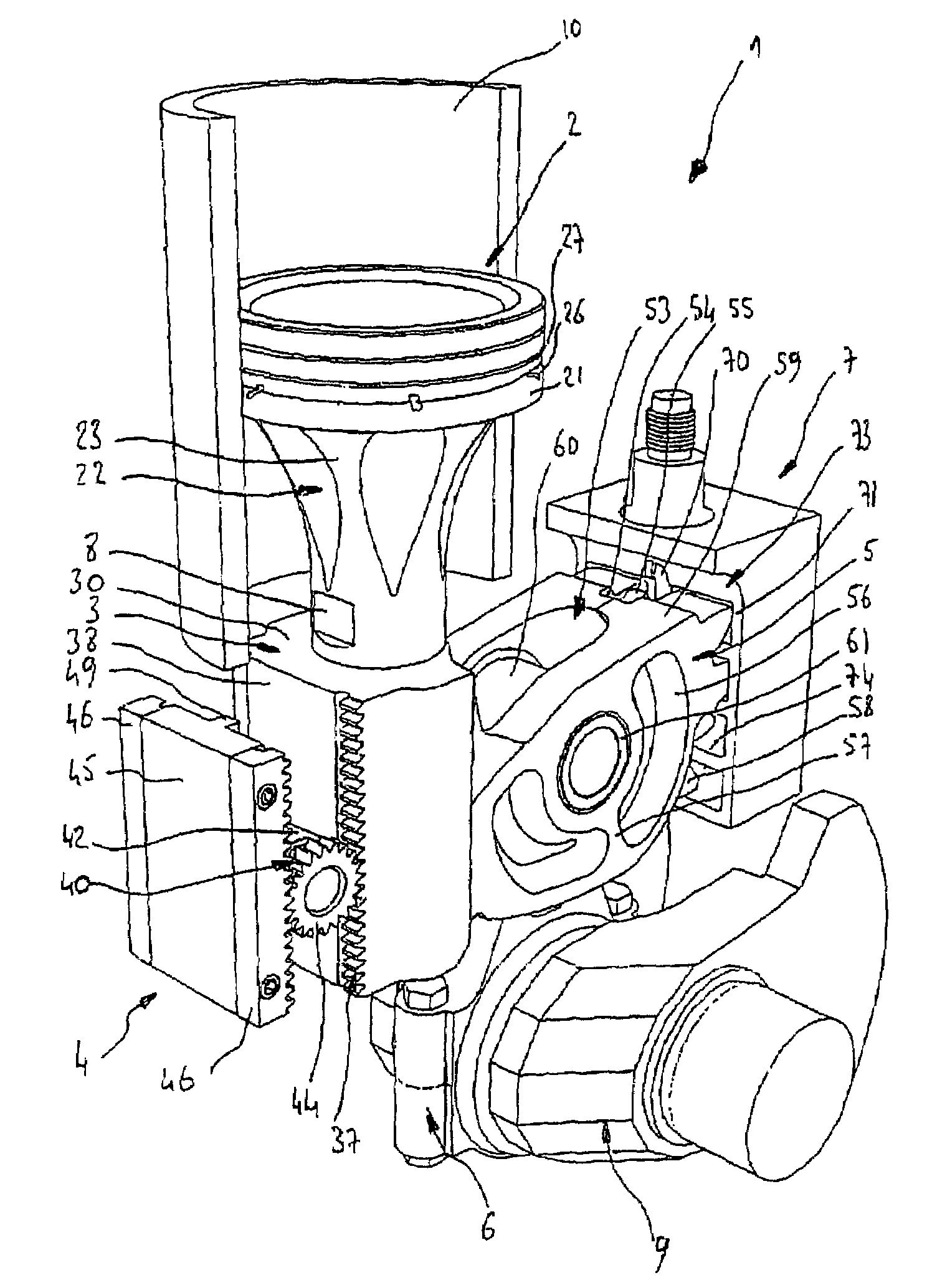
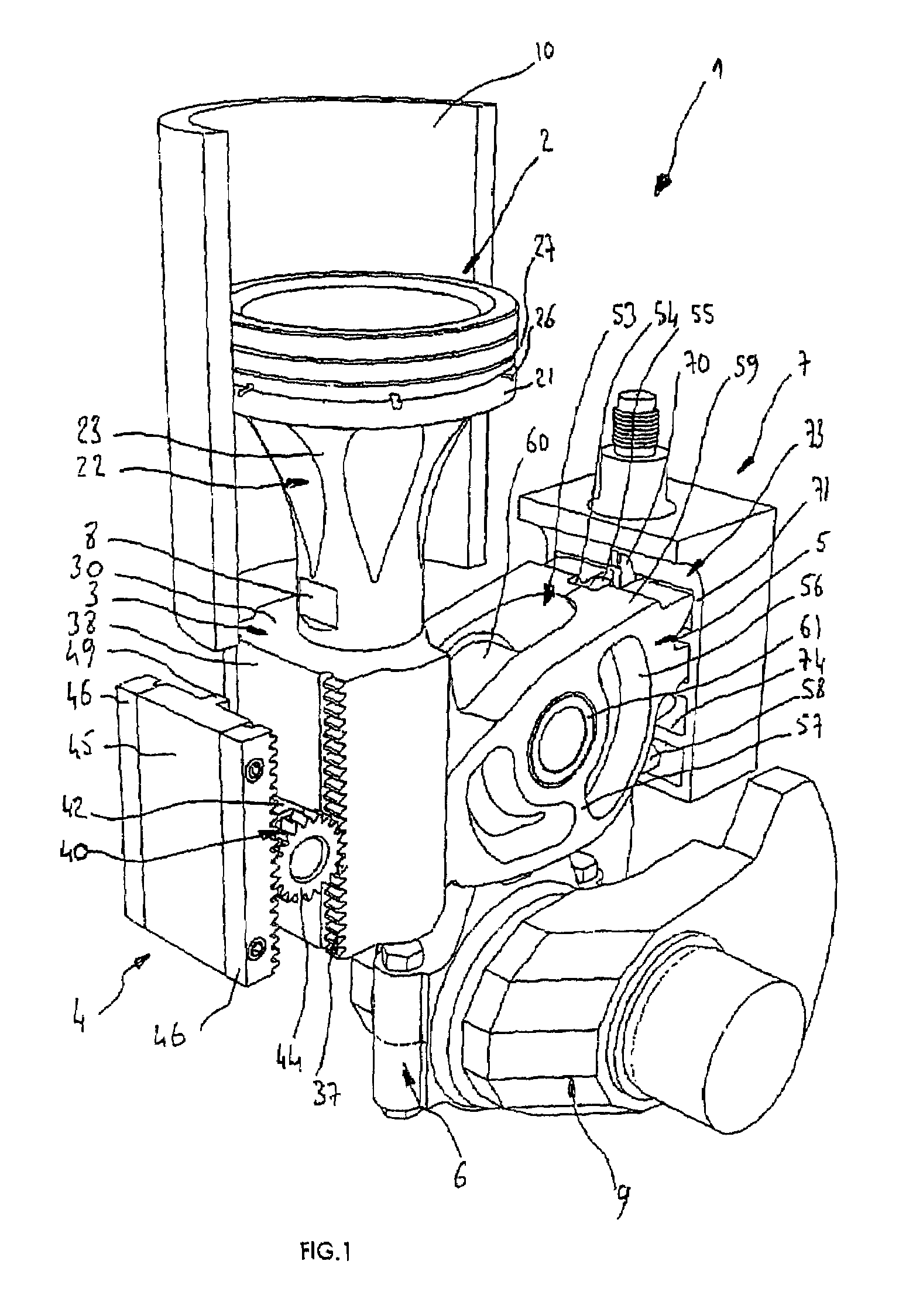
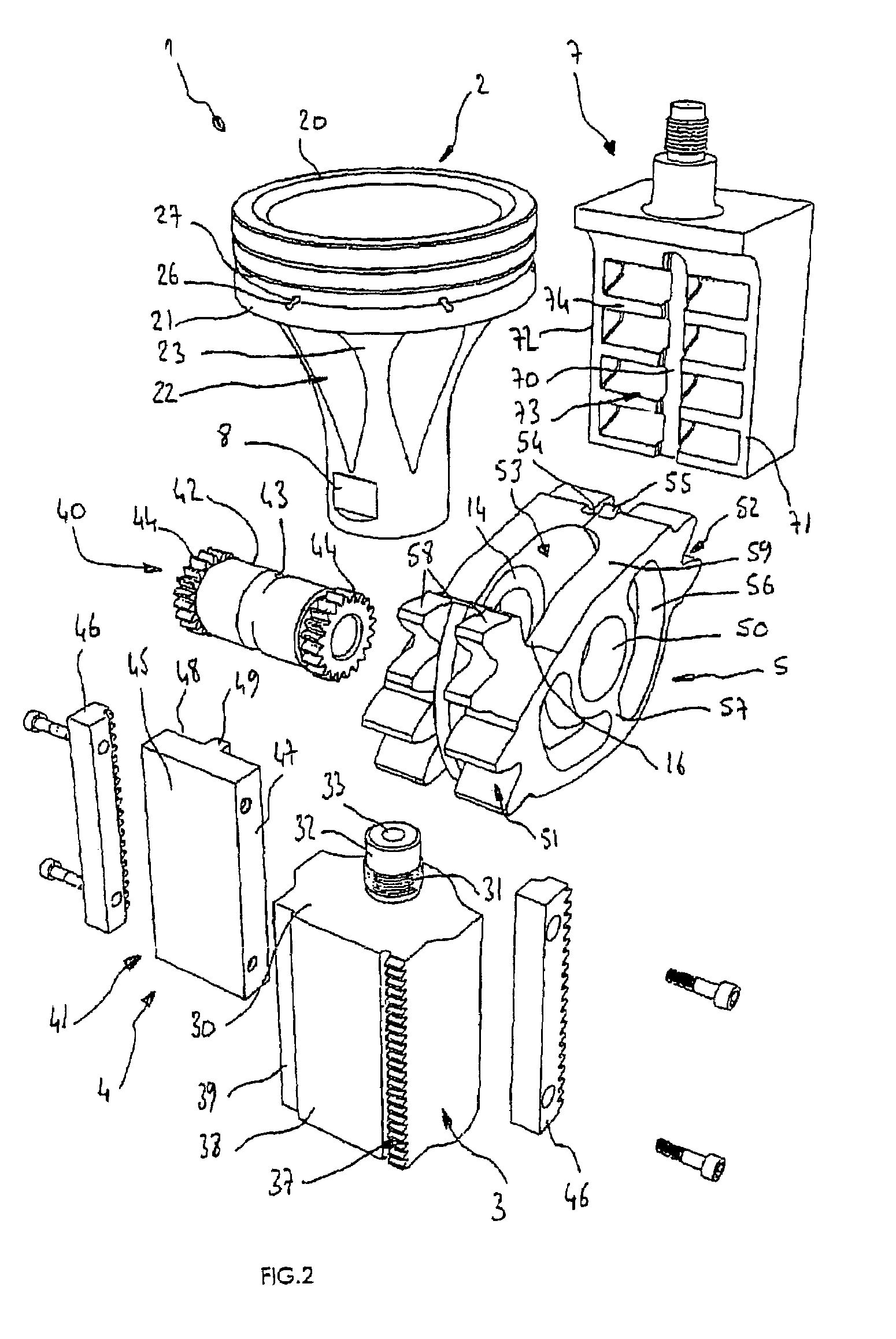
[0046]FIGS. 1 and 2 depict a mechanical transmission device 1 for a variable cylinder capacity engine comprising a piston 2 which is guided and driven in translational movement in a cylinder 10 of the engine block.

[0047]The piston 2 is secured at its lower part to a transmission member 3 which collaborates with a rolling guide device 4 and with a toothed wheel 5.

[0048]The toothed wheel 5 transmits the motion between a crankshaft 9 and the transmission member 3 secured to the piston 2 via a connecting rod 6 on which the toothed wheel 5 is mounted, by means of a connecting pin 61 which allows the toothed wheel 5 to pivot.

[0049]The toothed wheel 5 collaborates at the opposite end of the transmission member 3 with another member known as the control member 7 which is mounted in a recess or on a guide which are formed in the engine block.

[0050]The position of the control member 7 with respect to the engine block is afforded by a positioning device, not depicted, but described in a French...


PUM


Abstract

A mechanical transmission device for a variable cylinder capacity engine includes at least a cylinder (10) wherein moves a piston (2), which is integral in its lower portion with a transmission member (3) co-operating through a small-sized rack (37) with a roller bearing guide device (4) and through another large-sized rack (35) with a sprocket wheel (5) linked to a connecting rod (6), a control member (7) having a large-sized rack (73) co-operating with the sprocket wheel (5), elements for fixing (24, 31) the piston (2) on the transmission member (3) which provide a preload for clamping it and ensure its centring, linking elements (11, 12; 71, 72) for rigidifying the transmission (3) and control (7) members and for increasing the flexural strength of the teeth of the large-sized racks (35, 73) and elements for lightening (56) the sprocket wheel (5) which maintain its rigidity and load capacity.

Description

BACKGROUND OF THE INVENTION[0001]The present invention relates to a mechanical transmission device for guiding the piston or pistons of a variable cylinder capacity engine.[0002]The mechanical transmission device according to the present invention improves upon the transmission device described and protected in French patent application No. 98 15089 belonging to the Applicant.[0003]Specifically, the transmission device described in patent No. 98 15089 solved problems associated with the weight, rigidity and load-bearing capability of the various components. This patent also solved problems related to risks of the piston becoming seized in the cylinder and the vertical compactness of the engine as a whole.SUMMARY OF THE INVENTION[0004]The mechanical transmission device according to the present invention proposes solutions for lightening the racks and the toothed wheel while at the same time preserving their rigidity. The device also improves the guidance and fixing of the piston and ...

Claims


Application Information

Patent Timeline
IPC IPC(8): F02B75/04F01B9/04F01B9/08F01B31/14F02B75/32
CPCF01B9/047F02B75/045F16C33/60F16C5/00F16C33/306F02B75/048F02B75/04
Inventor RABHI, VIANNEY
Owner MCE 5 DEV 72 PART INTEREST
Why Eureka
Try Eureka