Tool for fine machining of optically active surfaces

Active Publication Date: 2006-06-27
SATISLOH GMBH
View PDF9 Cites 30 Cited by
  • Summary
  • Abstract
  • Description
  • Claims
  • Application Information

AI Technical Summary

Benefits of technology

[0010]The invention consequently is based on the object of creating a tool designed as simply as possible with reliable function for fine machining of optically active surfaces, in particular free form surfaces and toric surfaces on spectacle lenses, which has good adaptability to a wide range of geometries to be machined.
[0013]Because of the pressurisability of the elastic membrane via the pressure medium chamber, the axial mobility of the machining section of the membrane guided by the guide element, its tilt-mobility in relation to the guide element and the elastic deformability of the gaiter section of the membrane, the tool according to the invention can be adapted excellently to the geometry of the surface to be fine machined. At the same time the guide element of the tool according to the invention, by holding the machining section of the membrane in the transverse direction, ensures excellent guidance of the machining section close to the surface to be fine machined as the guide element is actively connected with the machining section so that the torsional and transverse forces necessary for machining can be reliably transferred to the surface to be fine machined while undesirable tilting forces are avoided. This excellent adaptability of the tool and very good guidance of the machining section of the membrane are not reduced by the torque transfer—necessary in any case—from the base body of the tool to its membrane as this torque transfer takes place via the gaiter section of the membrane i.e. functionally separately from the guide element. Also finally no complex construction of the tool is required. As a result of the design of the tool according to the invention, the tool can firstly adapt to virtually arbitrary geometries or curvatures of the surfaces to be fine machined and secondly reliably transfer the process forces necessary for machining for example to a fine grinding or polishing film. Also the tool is able to eliminate kinematic roughness of the pre-machined surface e.g. turning or milling grooves, by smoothing the structure.
[0014]In principle it is possible to form the machining section of the membrane so that it is flat when the membrane is without load. Preference is given however to a design in which the machining section of the membrane is preformed essentially spherical (convex or concave depending on requirements), which can easily be achieved on vulcanizing or casting of the membrane and whereby the machining section of the membrane can adapt even better to the surface to be fine machined.
[0016]In an advantageous embodiment of the invention it can be provided that the machining section of the membrane is stiffened by means of an areal reinforcement. This measure compensates in particular for the long wave unevenness which can result from the pre-machining structures (kinematic roughness in the form of turning or milling grooves), due to the greater removal of the raised parts of the turning or milling structure, whereby the fine machined surface is smoothed. Also the reinforcement ensures a better pressure distribution during fine machining. The reinforcement can essentially be preformed spherical which—compared with a flat form of the reinforcement which is also possible—ensures better deformability of the reinforcement and hence better adaptability of the machining section of the membrane to the surface to be machined.
[0018]In a further embodiment it can be provided that the reinforcement is comprised of a plastically deformable, metallic sheet section in particular a sheet section of a TiZn-based alloy. Use of such sheet metal as reinforcement prevents the machining section of the membrane from returning to its original shape, as it tries to do in principle because of its formation from elastomer material, whereby it is possible advantageously to deform the surface to be machined by means of the reinforced machining section in a manner sustainable at least during the fine machining process.
[0022]In order to achieve the maximum smoothness of guidance, between the guide element and the base body can be provided means for reducing friction. Here for example conventional slide bearings, slide bushes of e.g. PTFE or ball sockets can be used. In a preferred embodiment the receiving bore in the base body has at least one grease pocket as a means of reducing friction.

Problems solved by technology

The prior art has repeatedly found (e.g. DE 44 42 181 C1, EP 0 884 135 B1, DE 101 06 007 A1) that a disadvantage of rigid forming tools is that a large number of forming tools is required to fine machine the multiplicity of possible lens geometries occurring in prescription production of spectacle lenses (convex or concave curvatures from 0 to 17 diopters, where applicable with cylinder effect with up to 6 diopters) with possibly deviating refractive indices of the various materials.
Further difficulties occur in the trend for spectacles to use increasingly multi-focal lenses in the form of progressive focal lenses in which the distance vision area transforms progressively into the near vision area.
The softening and subsequent hardening of the plastically deformable mass however requires some time, so that this tool can only be used with restrictions in industrial production of prescription lenses.
One particular problem with these tools however is that these tools are very complex in design and consequently susceptible to fault.

Method used


Image

  • Tool for fine machining of optically active surfaces
  • Tool for fine machining of optically active surfaces
  • Tool for fine machining of optically active surfaces

Examples


Embodiment Construction

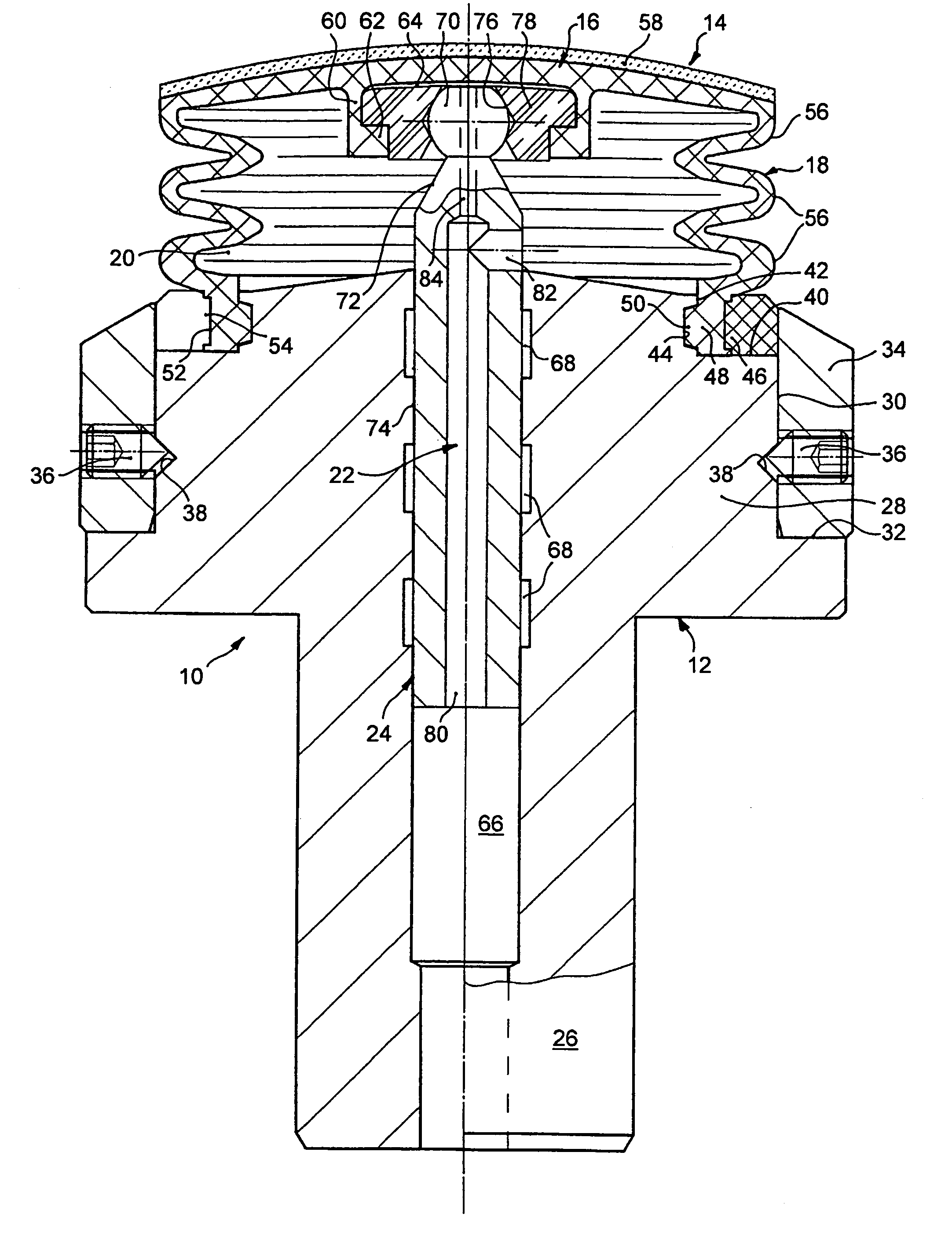
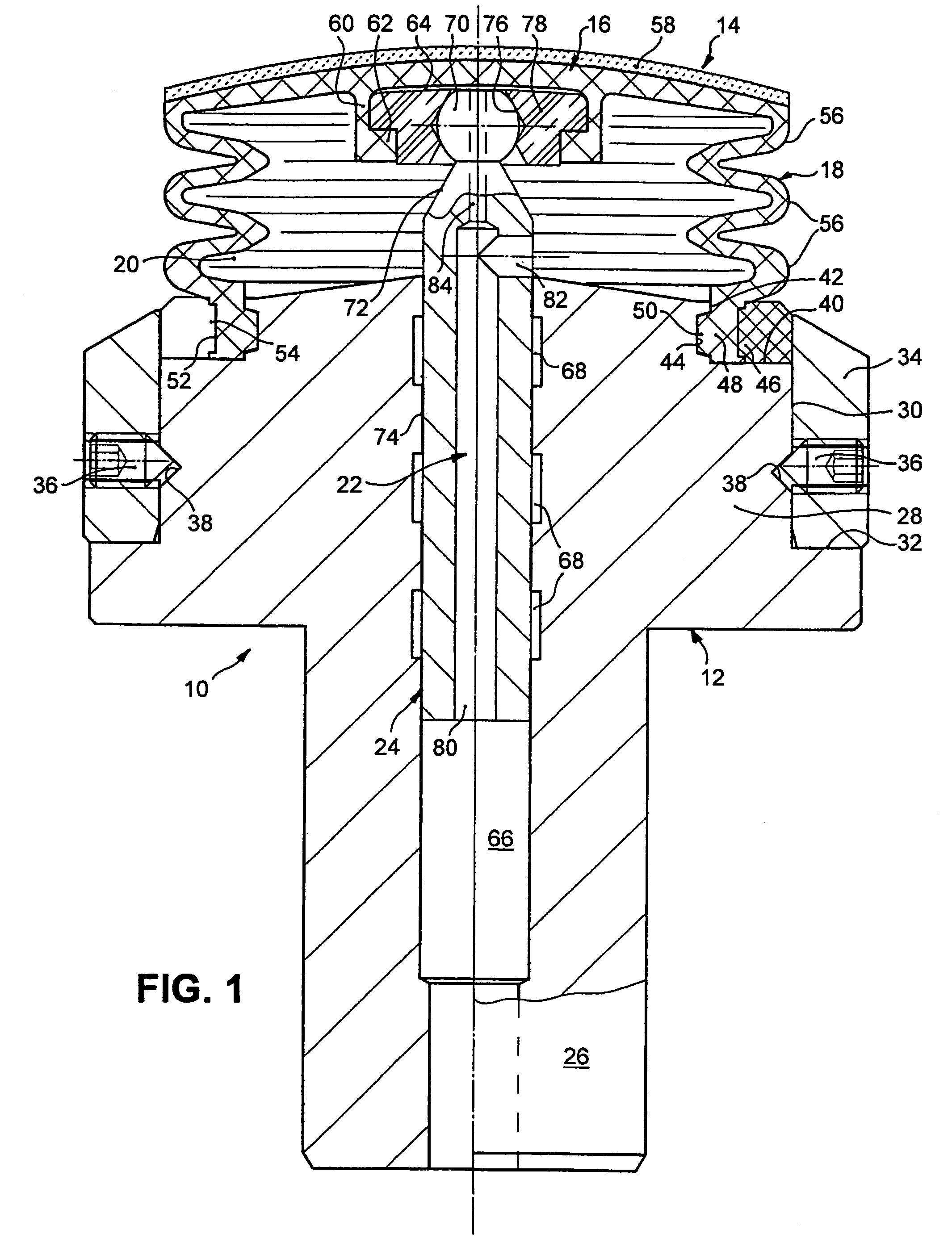
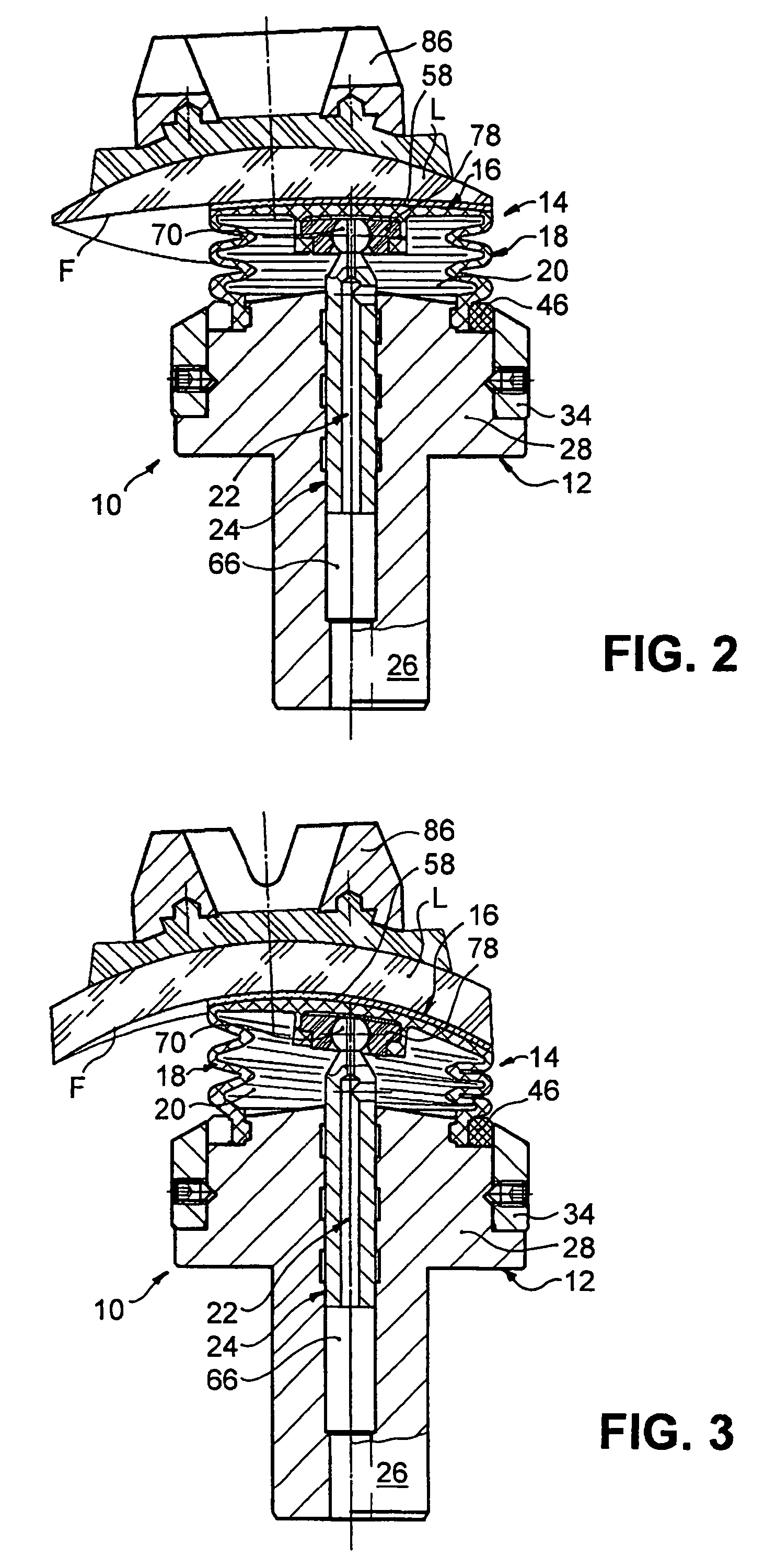
[0033]According to FIG. 1 a tool 10 for fine machining of optically active surfaces F, in particular for free form surfaces and toric surfaces on spectacle lenses L, has a base body 12, which can be attached to a tool spindle (not shown) of a machine tool known in itself (also not shown). Furthermore the tool 10 has an elastic membrane 14 that has a machining section 16 attached to which is a gaiter section 18, by means of which the membrane 14 is attached to the base body 12 so that it can rotate therewith. The base body 12 and the membrane 14 delimit a pressure medium chamber 20 of the tool 10 which via a channel 22 can be pressurized optionally with a suitable liquid or gaseous pressure medium (e.g. oil or compressed air with a pressure of around 0.2 to 0.6 bar), in order during machining of the optically active surface F to exert a machining pressure via the machining section 16. Guided longitudinally mobile on the base body 12 is a guide element 24, which as will be described i...


PUM


Abstract

A tool (10) is disclosed for fine machining of optically active surfaces (F), with a base body (12) that can be attached to a tool spindle of a machine tool, and an elastic membrane (14) that has a machining section (16) to which connects a gaiter section (18) by means of which the membrane is attached to the base body such that it can be rotated therewith. The base body and the membrane delimit a pressure medium chamber (20) which via a channel (22) can be optionally pressurized with a pressure medium in order to apply a machining pressure via the machining section during machining of the optically active surface. A guide element (24) guided longitudinally mobile on the base body is actively connected with the machining section so that the machining section can be moved in the longitudinal direction of the guide element and held in the transverse direction to the guide element, although under an elastic deformation of the gaiter section it is tilt-mobile in relation to the guide element. The result is a tool of simple design and reliable function which has an excellent adaptability to a wide range of geometries to be machined.

Description

BACKGROUND OF THE INVENTION[0001]The present invention relates to a tool for fine machining of optically active surfaces such as is used for example in lens production in fine machining of optical lenses. In particular the invention relates to a tool for fine machining of free form surfaces and toric surfaces on spectacle lenses.[0002]When the description below uses the term “spectacle lenses” as an example of optical workpieces, these refer not only to spectacle lenses of mineral glass but also to spectacle lenses of all other conventional materials e.g. polycarbonate, CR 39, HI index, etc. i.e. also plastics.[0003]Cutting machining of optically active surfaces of spectacle lenses can be roughly divided into two phases, namely first the pre-machining of the optically active surface to generate the prescription macro-geometry, and then the fine machining of the optical active surface to remove the traces of pre-machining and obtain the desired micro-geometry. Whereas pre-machining o...

Claims


Application Information

Patent Timeline
IPC IPC(8): B24B49/00B24B13/02
CPCB24B13/02B24B13/012
Inventor GRANZIERA, GILLESHEROLD, REINERPHILIPPS, PETERTRO.BETA., KARL-HEINZ
Owner SATISLOH GMBH
Why Eureka
Try Eureka