
Cylinder injection type internal combustion engine, control method for internal combustion engine, and fuel injection valve

a technology of internal combustion engine and control method, which is applied in the direction of electric control, machines/engines, liquid fuel feeders, etc., can solve the problems of reducing harmful components, limiting the efficiency of fuel injection, and reducing harmful components,

Inactive Publication Date: 2006-03-21
HITACHI LTD
View PDF47 Cites 60 Cited by
  • Summary
  • Abstract
  • Description
  • Claims
  • Application Information

AI Technical Summary

Benefits of technology

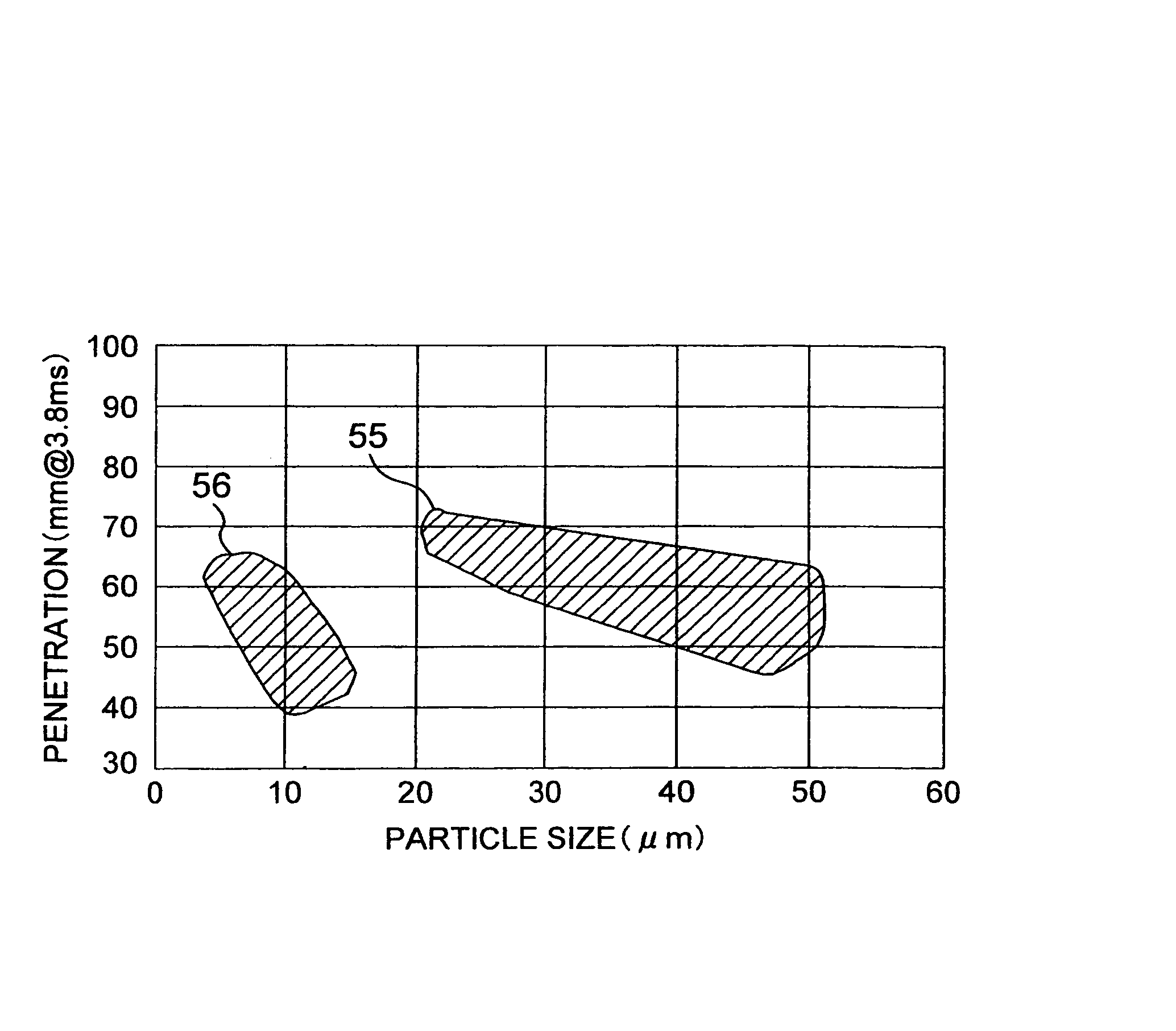
The patent text describes a cylinder injection type internal combustion engine and a method for controlling it. The engine includes a fuel injection valve that injects fuel directly into the combustion chamber. The engine is designed to achieve a stoichiometric air-fuel ratio and to improve fuel efficiency. The method includes injecting fuel at the beginning of the compression stroke and during the intake stroke, and optimizing the penetration of the fuel spray. The engine and method can be used to achieve a variety of objectives, such as improved fuel efficiency, reduced emissions, and reduced noise.

Problems solved by technology

However, even if any of the above-described combustion systems is used, most of fuel injected from the injection valve sticks to the piston and the wall surface in the combustion chamber, so that there are limitations in increasing fuel efficiency and reducing harmful components (for example, hydrocarbon) in exhaust gas due to the stratified charge operation.
Also, the stratified charge operation cannot be provided under a condition of 80 km / h or 2400 rpm and higher.

Method used


Image

  • Cylinder injection type internal combustion engine, control method for internal combustion engine, and fuel injection valve
  • Cylinder injection type internal combustion engine, control method for internal combustion engine, and fuel injection valve
  • Cylinder injection type internal combustion engine, control method for internal combustion engine, and fuel injection valve

Examples


Embodiment Construction

[0074]Embodiments of the present invention will be described with reference to the accompanying drawings.

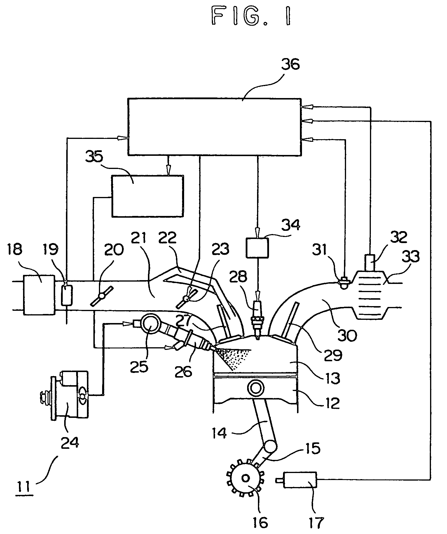
[0075]FIG. 1 shows one example of an engine system to which the present invention is applied. An engine 11 has a crank mechanism comprising of a connecting rod 14 and a crankshaft 15, and a combustion chamber 13 is formed by a piston 12 connected to the crank mechanism and an engine head of the engine 11. The combustion chamber 13 is sealed by intake valves 27, exhaust valves 29, an ignition plug 28, and a fuel injection valve 26 which are installed on the engine head.

[0076]In the engine 11, air necessary for combustion is sucked into the combustion chamber 13 by the reciprocating motion of the piston 12. Dirt and dust contained in the air to be sucked are removed by an air cleaner 18, and an intake air amount, which is a basis for calculating a fuel injection amount, is measured by an air flow sensor 19. The intake air amount is controlled by the degree of opening of a throttle ...


PUM


Abstract

There is provided a cylinder injection type internal combustion engine capable of performing stratified charge operation at the time of a vehicle speed of 120 km / h and / or an engine rotational speed of 3200 rpm to enhance the fuel efficiency and / or to observe the emission regulations. In the internal combustion engine, a stratum of air and / or air flow is formed between a fuel spray injected from an injection valve and the top face of a piston and / or the wall surface of a combustion chamber, and a face shape contrived to guide the air flow is formed on the top face of the piston.Also, the stratified charge operation can be performed even at the time of cold start or cranking.

Description

TECHNICAL FIELD[0001]The present invention relates to a cylinder injection type internal combustion engine in which fuel is injected directly into a combustion chamber of an internal combustion engine, a control method for an internal combustion engine, and a fuel injection valve.BACKGROUND ART[0002]In a conventional internal combustion engine of this type, a projecting portion is formed in the center on top face of a piston to form a depression called a cavity in the piston. Thereupon, fuel is injected from a fuel injection valve toward this cavity in the piston at the second half stage of the compression stroke of the internal combustion engine, so that a fuel spray repelled by the cavity is concentrated in the direction of ignition plug (Society of Automotive Engineers of Japan Annual Proceedings 976, Paper No. 9740307, October, 1997).[0003]Thus, the stratification of fuel in the combustion chamber is achieved, and combustion can be produced even with a lean mixture of an air-fue...

Claims


Application Information

Patent Timeline
Patent Type & Authority Patents(United States)
IPC IPC(8): F02B17/00F02B23/10F02B31/08F02B75/12F02D41/00F02D41/06F02D41/30F02D41/40F02F1/24F02F1/42F02M61/16F02M61/18F02M69/04
CPCF02B17/005F02B23/105F02B31/085F02D41/0002F02D41/06F02D41/3029F02F1/4214F02M45/02F02M61/162F02M61/1853F02M69/045F02B23/104Y02T10/123F02B2023/103F02B2023/106F02B2023/108F02B2031/003F02B2075/125F02B2275/48F02D41/402F02D2041/0015F02F2001/245F02M63/0225F05C2201/046Y02T10/125Y02T10/146Y02T10/42Y02T10/12Y02T10/40F02B31/08F02B23/10
Inventor SHIRAISHI, TAKUYANOGI, TOSHIHARUOHSUGA, MINORUNAKAYAMA, YOKOTOKUYASU, NOBORU
Owner HITACHI LTD
Learn More