Drainage member with expansion zones

a technology of expansion zone and draining member, which is applied in the direction of roads, construction, agriculture, etc., can solve the problems of difficult and expensive correction of wrinkles and other malformations of artificial turf, the expansion problem was exacerbated, and the drain could undergo significant expansion, so as to reduce the thickness of the base portion

Active Publication Date: 2006-03-21
AMERICAN WICK DRAIN CORP
View PDF16 Cites 74 Cited by
  • Summary
  • Abstract
  • Description
  • Claims
  • Application Information

AI Technical Summary

Benefits of technology

[0008]In one of the preferred embodiments of the present invention, the deformation of the flexible material may be caused by forming one or more u-shaped grooves extending generally transversely to the longitudinal extent of the base portion. In another preferred embodiment, the deformation may be caused by a plurality of holes or slots penetrating the base portion and extending along a line that is generally transverse to the longitudinal extent of the base portion. In yet another preferred embodiment, the deformation is caused by reducing the thickness of the flexible material forming the base portion along a width that is generally transverse to the longitudinal extent of the base portion.
[0010]The present invention also includes a method of forming a drainage member comprising the steps of providing a longitudinally extending flat base portion formed of flexible material; deforming the base portion to create a plurality of projections extending away from the flat base portion in spaced relation to one another to form drainage channels between the projections; and deforming the base portion to form expansion zones extending generally transversely of the longitudinal extent of the base portion so that the expansion zones will absorb longitudinal expansion of such material when it is exposed to heat without any significant increase in the longitudinal length of the drainage member.
[0011]In the preferred embodiment of the method of the present invention, the step of deforming the base portion to form expansion zones may include deforming the base portion into one or more v-shaped grooves extending transversely to the longitudinal extent of the base portion; or creating a plurality of holes or slots penetrating the base portion and extending along a line that is generally transverse to the longitudinal extent of the base portion; or reducing the thickness of the base portion along a width that is generally transverse to the longitudinal extent of the base portion.

Problems solved by technology

While these drainage systems and others like them are adequate for properly draining the water away from the artificial turf, they are costly, both from the standpoint of the costs of the materials themselves as well as the significant labor costs involved in properly installing the drainage system.
However, it was found that these drains could undergo significant expansion when they are exposed to typical heat conditions that are often encountered by artificial turf systems.
When these drainage systems were employed in the long lengths normally required for large areas of artificial turf, such as football or soccer fields, the expansion problem was exacerbated to the point that it created wrinkles and other malformations of the artificial turf which are difficult and expensive to correct.

Method used


Image

  • Drainage member with expansion zones
  • Drainage member with expansion zones
  • Drainage member with expansion zones

Examples


Embodiment Construction

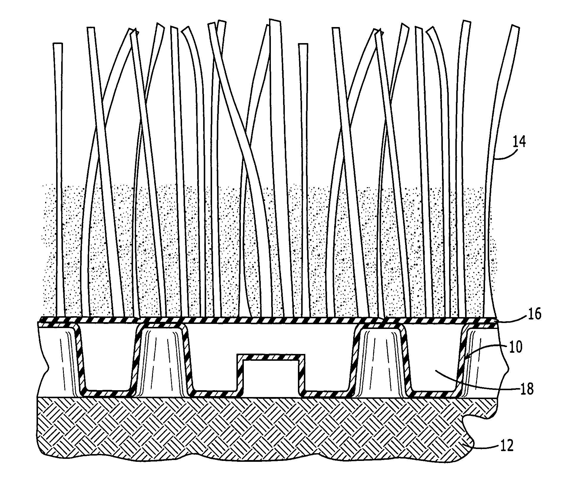
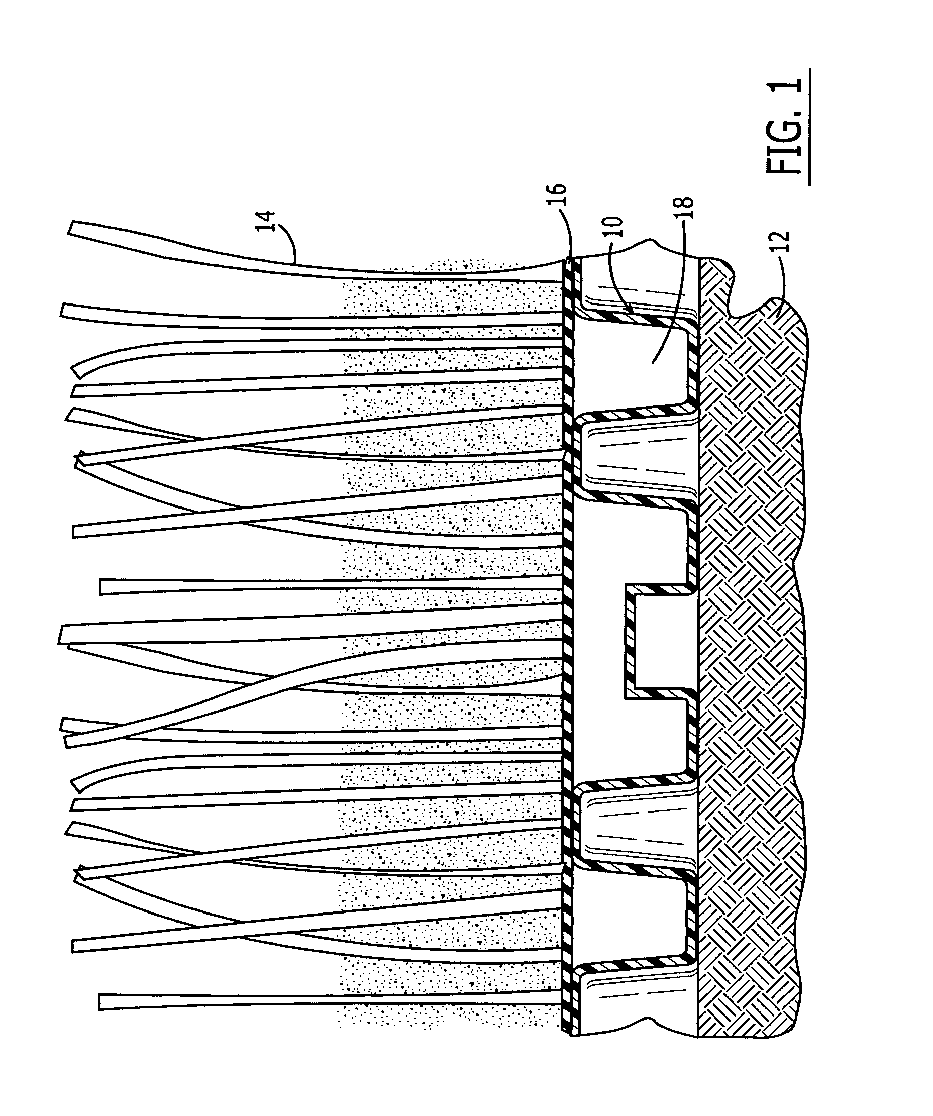
[0021]Looking now in greater detail at the accompanying drawings, FIG. 1 illustrates a typical environment in which a drainage member 10 according to the present invention is utilized. More specifically, FIG. 1 illustrates an artificial turf system which includes a foundation 12 which may be composed of virtually any type of firm material, and the drainage member 10 is supported on top of the foundation 12. Artificial grass or turf 14 is supported on top of the drainage member 10 so that the water collecting on or within the artificial turf 14 will penetrate the bottom layer 16 of the artificial turf and flow into the open areas or drainage channels 18 of the drainage member 10, as will be described in greater detail below. The water which collects in the drainage member 10 is channeled so that it will flow away from the artificial turf through a conventional water discharge conduit or the like (not shown) in a manner that is well known in the art. It is expressly understood that th...


PUM


Abstract

A drainage member for use in promoting the drainage of water away from a substrate positioned adjacent the drainage member which includes an elongated, longitudinally extending base formed of a flexible material and having a plurality of outwardly extending projections. The projections are spaced from one another to form drainage channels between the projections. The elongated base has a plurality of expansion zones formed of the flexible material and extending generally transversely of the longitudinal extent thereof, the expansion zones comprising a deformation of the flexible material that absorbs longitudinal expansion of such material when it is exposed to heat without any significant increase in the longitudinal length of the drainage member.

Description

BACKGROUND OF THE INVENTION[0001]The present invention relates generally to systems for draining water away from a generally flat substrate, and more particularly to a drainage member that is designed to be located beneath an upper layer of material, such as artificial turf, synthetic turf or the like, for draining away water that seeps through such upper layer.[0002]It has been known for some time that natural grass can be replaced with artificial or synthetic turf in many environments. In general, artificial turf requires considerably less maintenance than natural grass or sod, and it can often be used in locations where natural grass cannot be grown. Artificial turf systems can take various forms, and one typical system is disclosed in U.S. Pat. No. 5,601,886 in which the artificial turf is fabricated in a tufting machine so that artificial turf filaments penetrate backing material.[0003]While there are many applications for artificial turf, perhaps the most common are on athleti...

Claims


Application Information

Patent Timeline
Patent Type & Authority Patents(United States)
IPC IPC(8): E02B11/00
CPCE02B11/005E01C13/08E01C13/02
Inventor MORRIS, R. SCOTT
Owner AMERICAN WICK DRAIN CORP
Why Eureka
Try Eureka