
Quick release volume control inserts for molding machines

a molding machine and volume control technology, applied in the field of quick change inserts, can solve the problems of requiring special tools, requiring installation and removal of inserts, and being commercially undesirable for containers to appear less than full,

Active Publication Date: 2006-03-21
UNILOY INC
View PDF12 Cites 10 Cited by
  • Summary
  • Abstract
  • Description
  • Claims
  • Application Information

AI Technical Summary

Benefits of technology

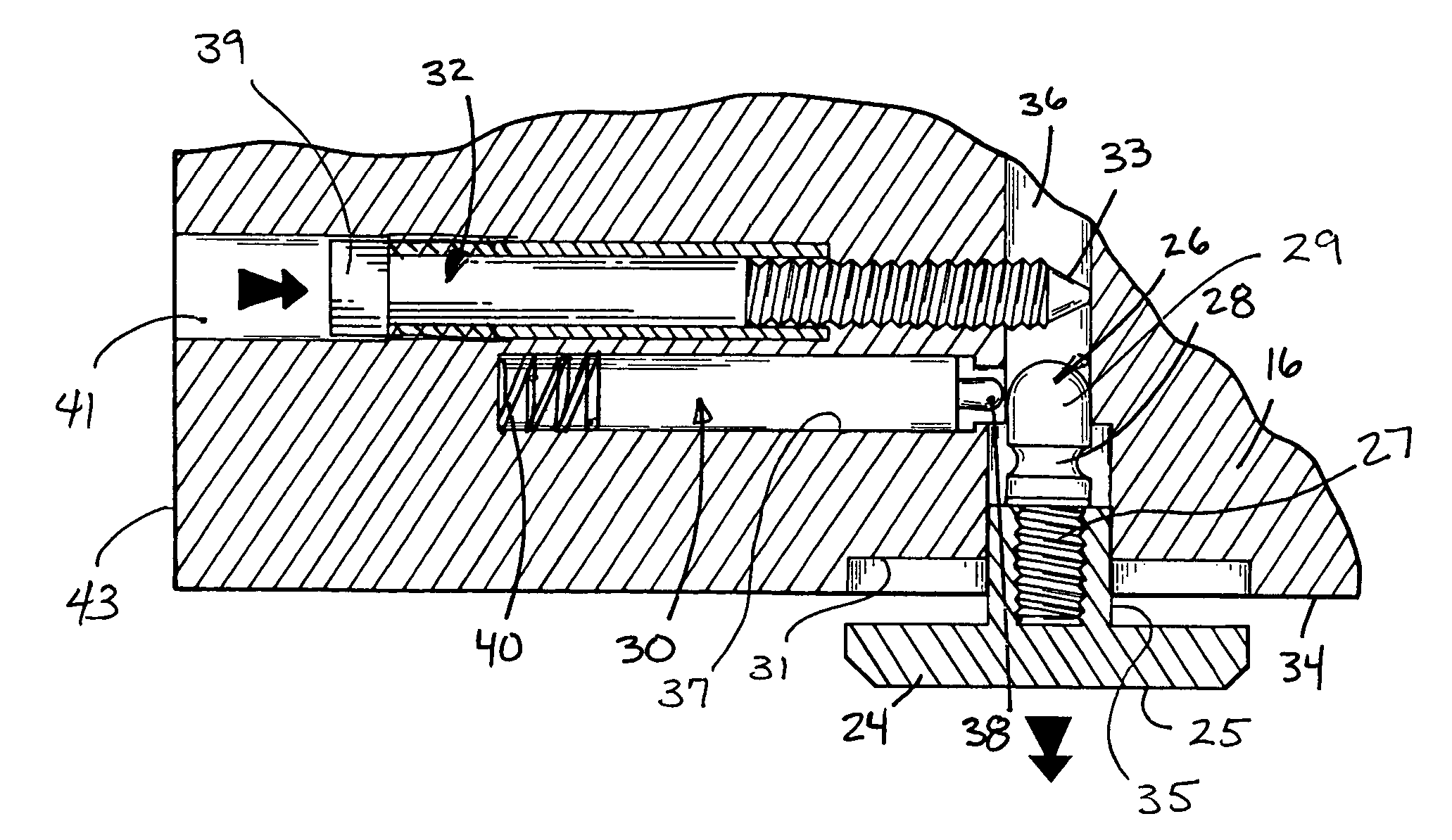
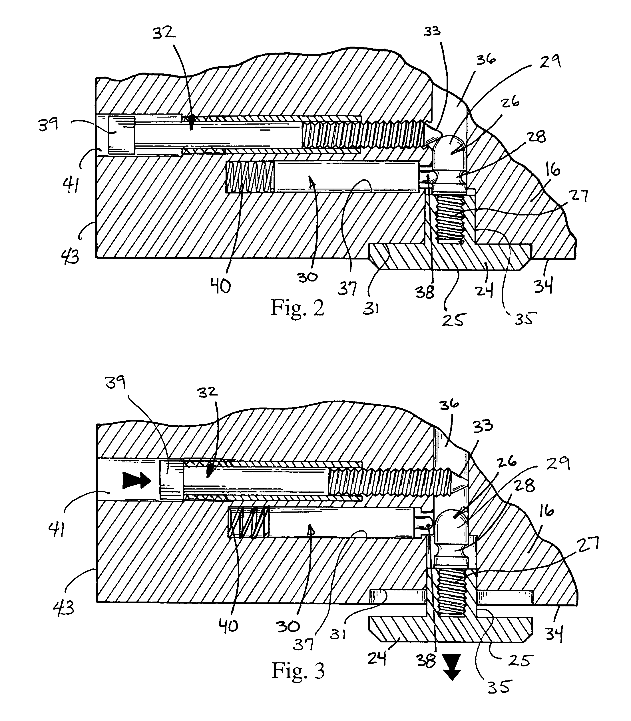
[0008]In satisfying the above need, as well as overcoming the enumerated and other limitations of the prior art, the current invention provides a molding machine and a mold assembly having a quick change volume control insert. The volume control insert can be changed without disassembly of the mold or use of special tools.

Problems solved by technology

The process of blow molding plastic containers is susceptible to many environmental and process variables, such as temperature, moisture, and pressure.
Therefore it is commercially undesirable for containers to appear less than full.
This had the disadvantage that the bolt fastening the insert would often be accessible only from the back of the mold, requiring complete removal of the mold from the machine in order to change the mold insert.
The disadvantage of the pneumatic method is that the installation and removal of the insert requires a complex procedure and special tools, including a pneumatic pump.
Additionally, there is a risk that the insert can fall out of the mold if the insert is not correctly installed or if the pneumatic system loses pressure, since a continuous vacuum draw is not provided.

Method used


Image

  • Quick release volume control inserts for molding machines
  • Quick release volume control inserts for molding machines
  • Quick release volume control inserts for molding machines

Examples


Embodiment Construction

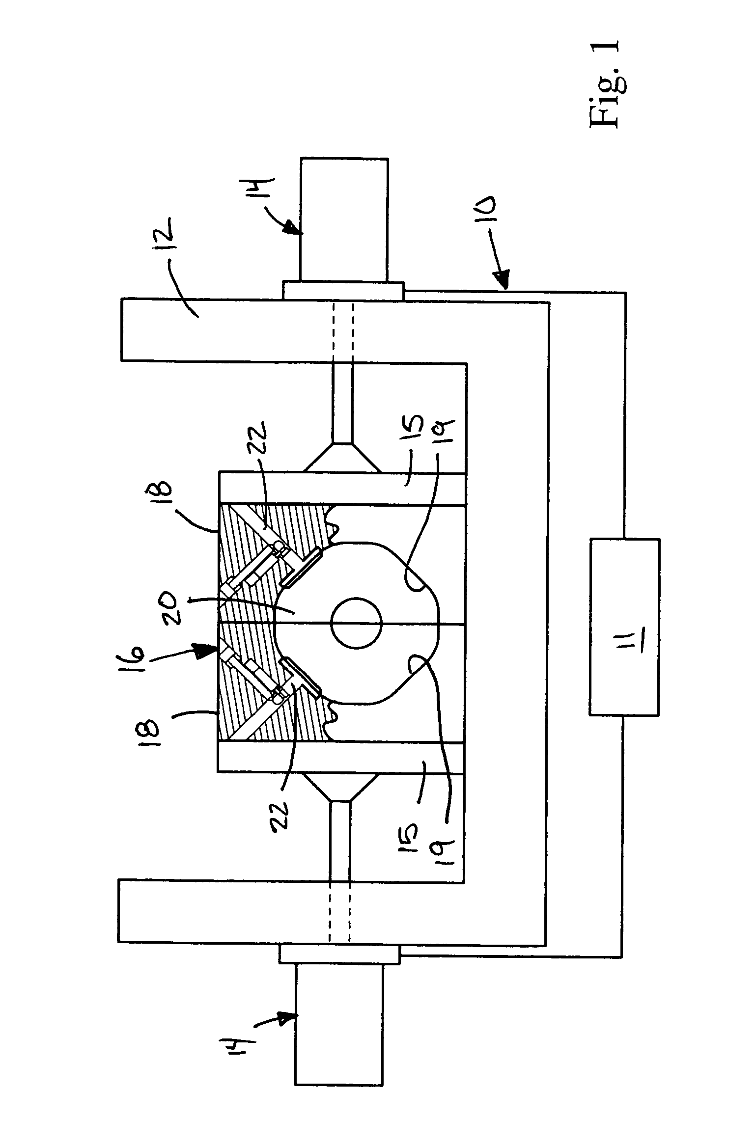
[0017]Referring now to the drawings, a molding machine 10 embodying the principles of the present invention is diagrammatically illustrated therein and designated at 10. As its primary components, the molding machine 10 includes a controller 11, a frame 12, actuators 14, platens 15 and a mold 16.

[0018]The actuators 14 are supported by the frame 12. Upon receiving appropriate signals from the controller 11, the actuators 14 cause the platens 15, which carry the mold 16, to move between open and closed positions during various stages of the molding process. The mold 16 itself is made up of two mold halves 18, having surfaces 19 which cooperate to form a mold cavity 20. Each mold half 18 is attached to a platen 15 coupled to an actuator 14 which closes the mold 16 during molding and separates the mold halves 18 to enable removal the molded container. The molding machine 10 is only diagrammatically shown in FIG. 1 since one skilled in this field will readily understand that the machine ...


PUM

PropertyMeasurementUnit
volumeaaaaaaaaaa
shapeaaaaaaaaaa
forceaaaaaaaaaa

Abstract

The present invention provides a molding machine and a mold assembly having a quick change volume control insert. The volume control insert can be changed without disassembly of the mold or use of special tools. The molding machine includes a mold, a mold insert, a locking member, and a release member. The mold insert is received in one of the mold halves and further includes a mold detail defining a portion of the mold cavity, and a retention member. A locking member engages the retention member when the mold detail is received within the mold half. The release member, accessible from the exterior of the mold half, and is adapted to disengage the locking member from the retention member, allowing the mold detail to be removed.

Description

BACKGROUND[0001]1. Field of the Invention[0002]The present invention relates to molding machines. More specifically, the invention relates to quick change inserts provided in the cavity of a mold.[0003]2. Description of the Related Art[0004]The process of blow molding plastic containers is susceptible to many environmental and process variables, such as temperature, moisture, and pressure. These variables will affect the apparent volume of the container once filled with liquid. If the volume of the container is slightly larger than designed, the container may not appear full when the specified amount of liquid is dispensed into the container. For example, if the volume of a milk container is larger than one gallon, when the container is properly filled with one gallon of milk, the container will appear to be less than full, and a consumer might assume that the container has less than a full gallon of milk and not purchase that container. Therefore it is commercially undesirable for ...

Claims


Application Information

Patent Timeline
Patent Type & Authority Patents(United States)
IPC IPC(8): B29C49/52B29C33/30B29C49/48
CPCB29C33/306B29C2049/4858B29C49/48
Inventor HALL, GREGORY T
Owner UNILOY INC
Learn More