Needle insertion device

a needle insertion and needle technology, applied in the field of needle insertion devices, can solve the problems of increasing the risk of accidental needle injury, affecting the actual user's and often problematic actual user-performed piercing of the tissue with the needl

Active Publication Date: 2006-03-21
NOVO NORDISK AS
View PDF25 Cites 277 Cited by
  • Summary
  • Abstract
  • Description
  • Claims
  • Application Information

AI Technical Summary

Benefits of technology

[0020]Having regard to the above-identified problems, it is an object of the present invention to provide a skin-mountable needle insertion device which reduces the likelihood that a user comes into contact with an infusion needle or any other transcutaneously insertable structure prior to use or when the device is removed from the skin of the user after a period of use.
[0021]The present invention is based on the concept that the risk of accidental contact with a needle or similar structure can be reduced if the needle as such is arranged inside the device, i.e. the distal pointed end is arranged such that it does not protrude from the lower skin-contacting surface as defined by the general plane of that surface. As the needle does not protrude from the lower surface, normally no insertion would take place when the device is mounted onto the skin of the user, however, corresponding to the present invention, the skin portion corresponding to the intended site of needle insertion is pulled up against the needle by adhesive means.
[0032]In order to further reduce the likelihood of needle injury, the mounting surface and the needle may be configured such that even when the needle projects through the needle aperture, the device can be arranged on a planar surface without the needle coming into contact with that surface.

Problems solved by technology

The first class comprises durable infusion pumps which are relatively expensive pumps intended for 3–4 years use, for which reason the initial cost for such a pump often is a barrier to this type of therapy.
Although this configuration provides a simple and cost-effective solution, it has a number of drawbacks.
For example, the actual user-performed piercing of the tissue with the needle is often problematic as people who are not experts in medicine are usually insufficiently practised to place such a needle correctly and they often suffer from a fear of the likely pain.
Further, the permanently projecting needle increases the risk for accidental needle injuries.
Although in the known devices it may be possible to withdraw either the needle into the housing after use or extending a protecting element to cover the needle, this operation may not necessarily be performed when the device is removed from the skin of the user, this resulting in the used infusion needle projecting from the lower surface of the device.

Method used


Image

  • Needle insertion device
  • Needle insertion device
  • Needle insertion device

Examples


first embodiment

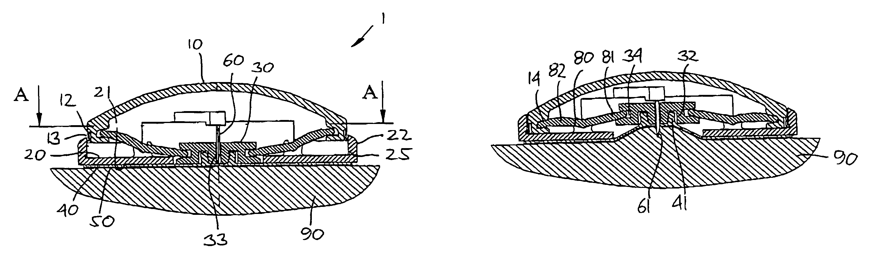
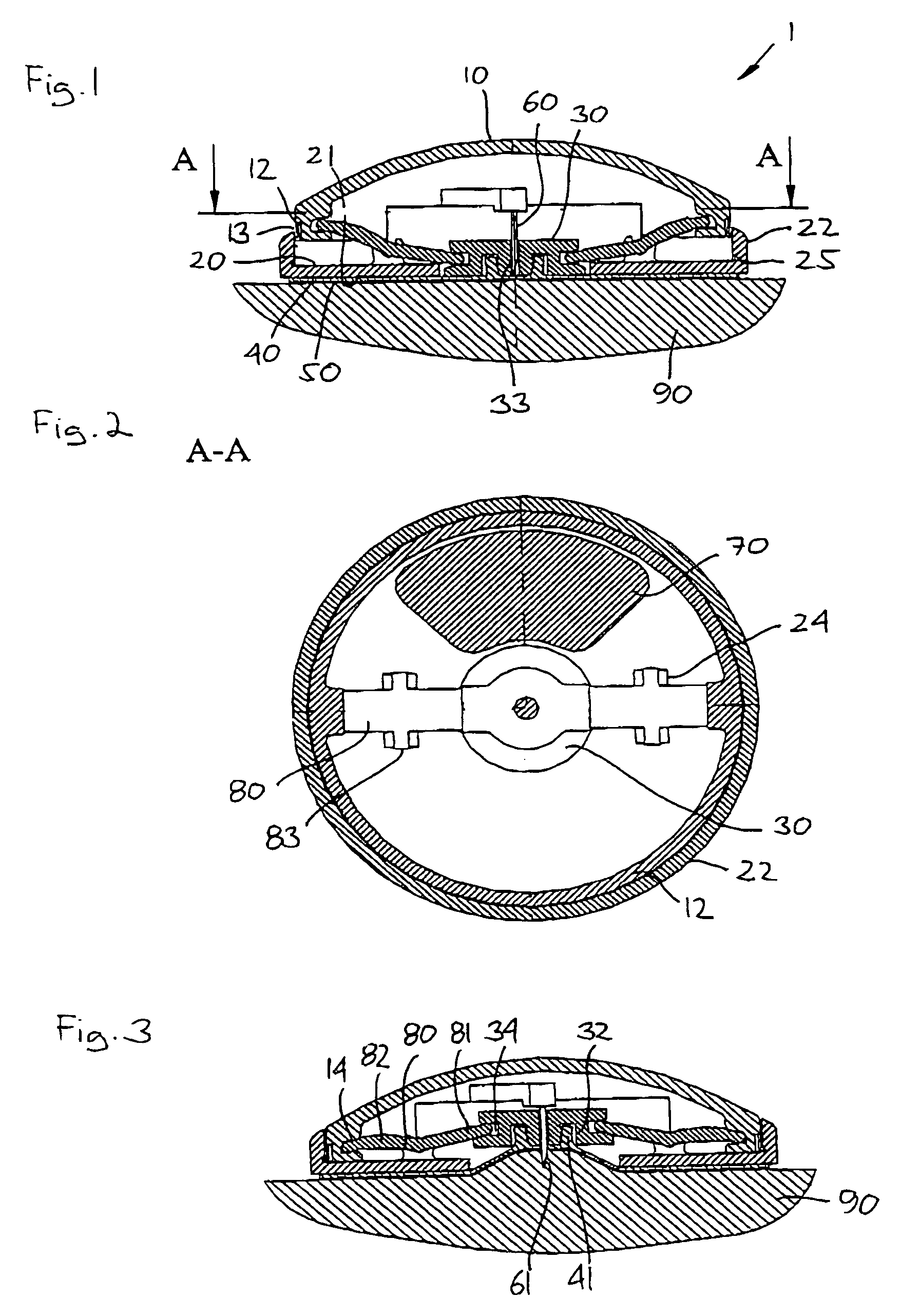
[0050]FIGS. 1 and 3 show in vertical respectively horizontal section a schematic representation of the invention. Correspondingly, the configuration of the different structures as well as there relative dimensions are intended to serve illustrative purposes only.

[0051]More specifically, an infusion device 1 comprises a housing having an upper member 10 a lower base plate member 20, and an aperture member 30, the three members in combination defining the general exterior configuration of the device.

[0052]The base plate member comprises a lower mounting surface 21 adapted for application towards the skin of a user, the mounting surface defining a general plane which in the shown embodiment is planar. The base plate member is provided with an upstanding peripheral flange portion 22 and a central opening 23 in which the aperture member 30 is arranged. On the upper side the base plate member is provided with a pair of axle gripping means 24 (to be described in greater detail below). The ...

second embodiment

[0061]Next, with reference to FIGS. 4 and 5, use of the above-described second embodiment will be described. The infusion device 101 is supplied in an initial configuration with a release liner covering the adhesive layer. After removing the liner (as shown in FIG. 1), the user grips the device on the peripheral portion of the upper member and gently adheres the central aperture portion of the base plate member to the skin 190. As more pressure is applied to the device, the downwardly curved lower surface will be forced against the skin, however, at a given time the pressure on the central portion of the bi-staple disc member will overcome the necessary transition force, and the disc will swiftly flex upwardly to its second position in a snap action-like manner, pulling the skin towards the needle, whereby the needle is introduced subcutaneously into the skin of the user, this as shown in FIG. 5.

[0062]After use the infusion device is removed by simply pulling it off the skin. When t...

third embodiment

[0063]With reference to FIGS. 1–5 embodiments of the invention has been described in which the needle insertion device of the invention has been incorporated into an infusion device, however, with reference to FIGS. 6 and 7 a third embodiment will be described in which the needle insertion device of the invention has been incorporated into a sensor device 201.

[0064]The third embodiment has the same general configuration as the second embodiment comprising an upper member 210 and a lower base plate member 220, however, instead of an infusion needle, a needle-formed sensor member 260 is provided comprising a distal sensor element (261) capable of being influenced by a body substance and producing a signal corresponding thereto. The signal from the sensor element is conducted through the needle sensor to a control means 270 adapted to receive the signals from the sensor element and generate signals in response thereto providing an indication of the desired body substance parameter, e.g...


PUM


Abstract

The invention relates to a needle insertion device comprising a housing with a mounting surface adapted for application to the skin of a subject, where the mounting surface defines a general plane and has a needle aperture formed therein. Adhesive means is arranged on the mounting surface for adhering the insertion device to the skin of the subject, the adhesive means surrounding the needle aperture. A needle comprises a distal pointed end adapted to penetrate the skin of the subject, the pointed end being arranged within the housing in respect of the general plane. The mounting surface surrounding the needle aperture is moveable between a first position in which the pointed end of the needle is arranged within the housing, and a second position in which the pointed end of the needle projects through the needle aperture, thereby pulling the skin portion corresponding to the intended site of needle insertion against the needle.

Description

CROSS REFERENCE TO RELATED APPLICATIONS[0001]This application claims priority under 35 U.S.C. 119 of Danish application no. PA 2002 01493 filed Oct. 7, 2002 and U.S. provisional application No. 60 / 419,310 filed Oct. 17, 2002, the contents of both are fully incorporated herein by reference.[0002]The present invention generally relates to the insertion of needles or needle-like members. More specifically, the invention relates to a needle device for placing a needle transcutaneously at a selected site within the body of a patient and having a contact surface for attaching the device to a patient's skin. Especially, the invention relates to insertion of an infusion needle for the infusion of a drug, to insertion of a needle-formed sensor, as well as to insertion of an insertion needles for easy transcutaneous placement of a transcutaneous device such as a sensor.BACKGROUND OF THE INVENTION[0003]In the disclosure of the present invention reference is mostly made to the treatment of diab...

Claims


Application Information

Patent Timeline
Patent Type & Authority Patents(United States)
IPC IPC(8): A61M37/00A61M5/00A61M5/142
CPCA61M5/14248
Inventor BENGTSSON, HENRIK
Owner NOVO NORDISK AS
Why Eureka
Try Eureka