Apparatus and method for the testing of circuit boards, and test probe for this apparatus and this method

a technology for circuit boards and test probes, applied in the direction of electronic circuit testing, measurement devices, instruments, etc., can solve the problems of inability to use circuit boards for actual testing, adverse effects of calibration processes on throughput, and both calibration processes take up a considerable amount of time, so as to increase the throughput of circuit boards

Inactive Publication Date: 2006-03-21
ATG TEST SYST
View PDF22 Cites 154 Cited by
  • Summary
  • Abstract
  • Description
  • Claims
  • Application Information

AI Technical Summary

Benefits of technology

[0014]The invention can be used to improve the reliability with which test points are contacted by an apparatus and a method for the testing of circuit boards by means of test fingers, with less calibration time than is required for conventional finger testers. The invention is also based on the problem of providing a test probe for this apparatus and this method.
[0018]With the apparatus according to the invention and the method according to the invention, the calibration process is performed together with the actual testing or measuring process, without any considerably delay to the latter. This represents a significant acceleration in the method of testing circuit boards using a finger tester, and considerably increases the throughput of circuit boards to be tested.

Problems solved by technology

Both calibration processes take up a considerable amount of time, which cannot be used for actual testing of circuit boards.
Consequently, in the testing of circuit boards, these calibration processes have an adverse effect on throughput.

Method used


Image

  • Apparatus and method for the testing of circuit boards, and test probe for this apparatus and this method
  • Apparatus and method for the testing of circuit boards, and test probe for this apparatus and this method
  • Apparatus and method for the testing of circuit boards, and test probe for this apparatus and this method

Examples


Embodiment Construction

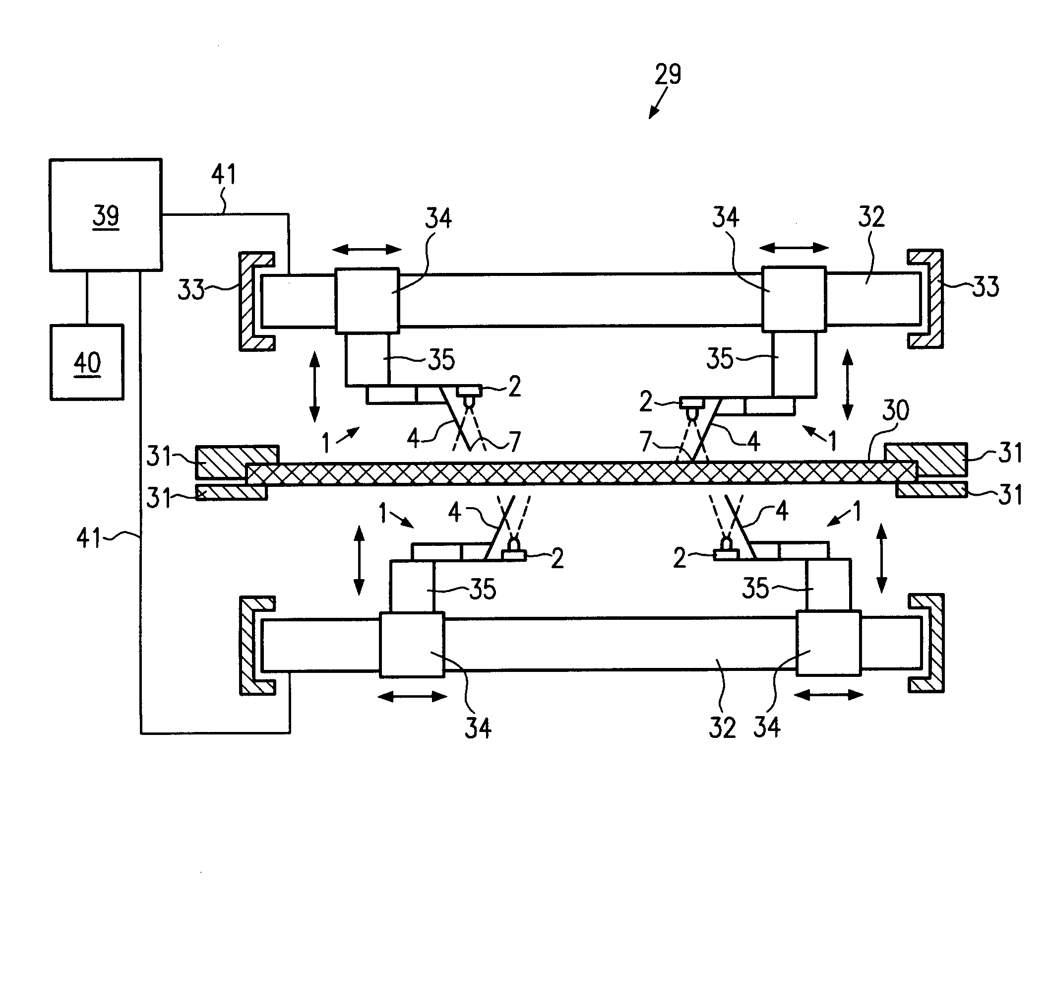
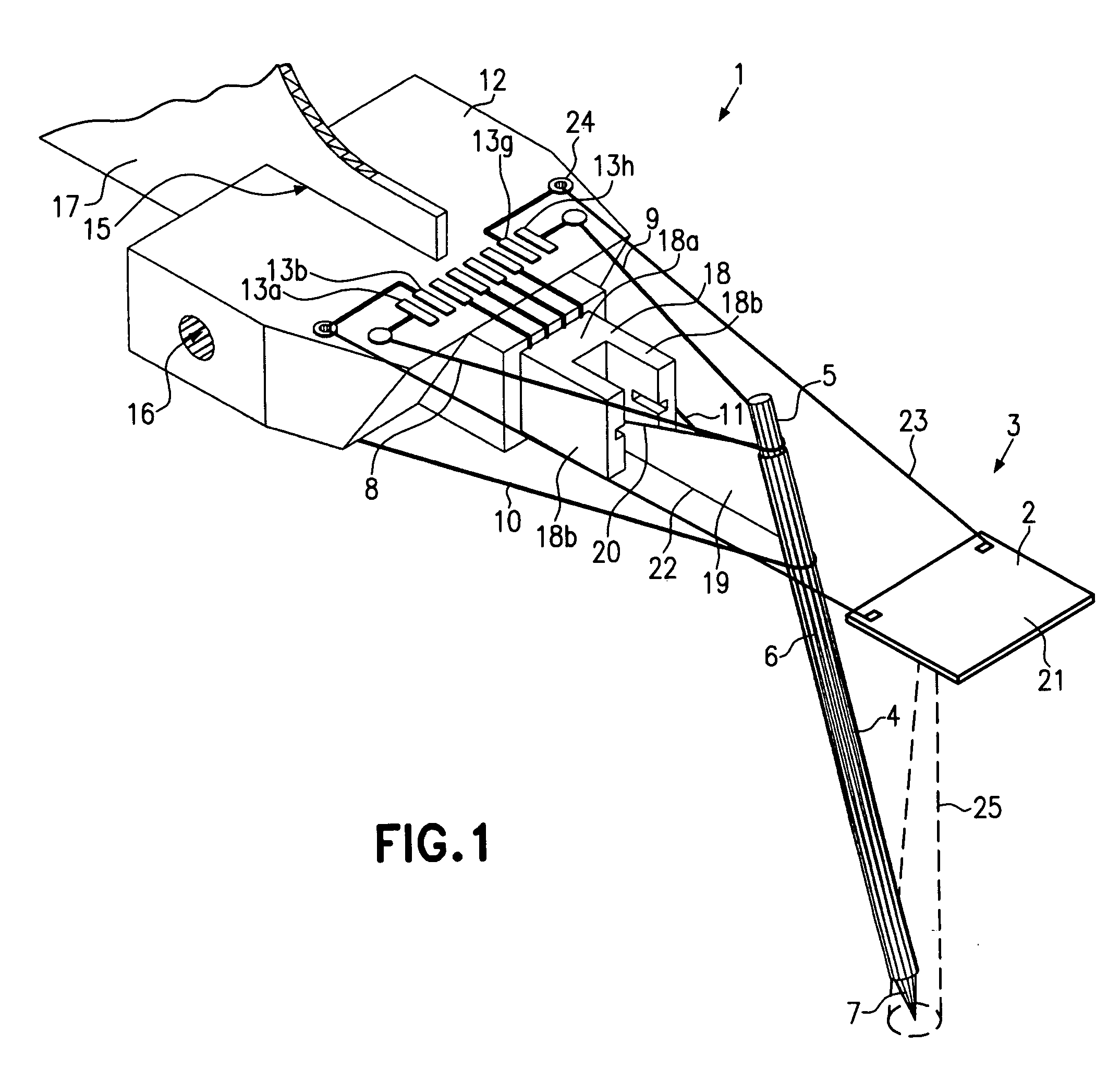
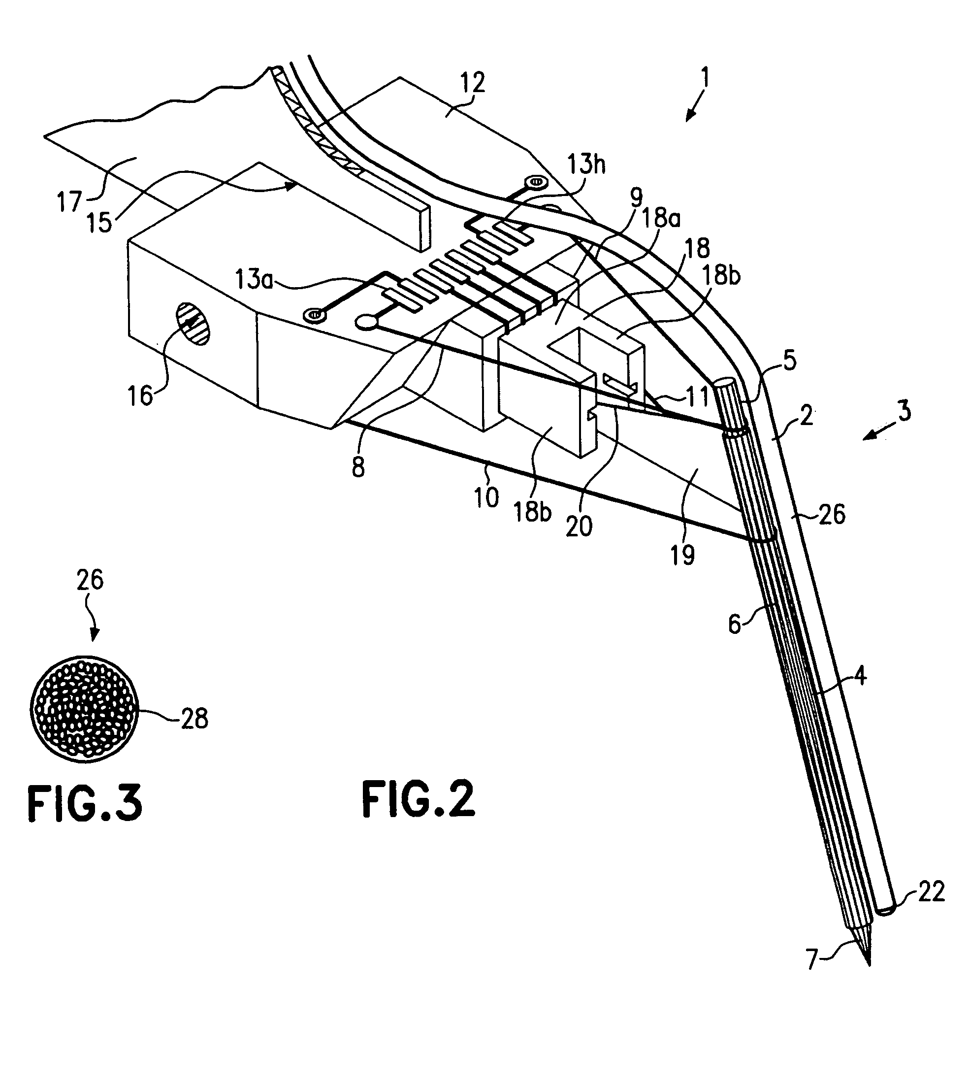
[0029]FIGS. 1 and 2 show two different embodiments of test probes 1, which have been constructed according to the principles of the present invention.

[0030]Each of these test probes 1 has an optical receiver device 2 of an optical detection device 3. The basic structure of this test probe 1, apart from the optical receiver device, is described in U.S. patent application Ser. No. 10 / 859,759, filed on Jun. 3, 2004, entitled Test Probe For Finger Tester and Corresponding Finger Tester, by Victor Romanov, which is incorporated herein in its entirety by this reference. (See also German patent application DE 101 60 119.0.) Reference is therefore made to this patent application.

[0031]The test probe 1 has a test needle 4, formed in the present embodiment by a needle 5 with a diameter d of 0.3–0.5 millimeters (mm). The needle 5 is mad of, for example, steel or tungsten. The needle 5 is coated with an insulating layer, for example polytetrafluoroethylene, also known as Teflon® coating. The co...


PUM


Abstract

An apparatus and a method for the testing of circuit boards, together with a test probe for this apparatus and this method, in which the contact tips of a test finger of a finger tester are monitored during the testing process by an optical detection device and their movement, at least when approaching a part of the circuit board test points of a circuit board to be tested, is corrected on the basis of the result determined by the optical detection device in such a way that the contact tip makes reliable contact with the circuit board test point concerned. The correction data hereby obtained may be used in the calculation of calibration data.

Description

RELATED APPLICATIONS[0001]This application is a Continuation of PCT / EP 03 / 04468, filed Apr. 29, 2003 (which was published in German under PCT Article 21(2) as International Publication No. WO 03 / 096037 A1), which claims priority to German Application No. DE 102 20 343.1, filed May 7, 2002, both applications being incorporated herein by reference in their entirety.BACKGROUND OF THE INVENTION[0002]Testers for the testing of circuit boards may in principle be divided into two groups, those with finger testers and those with parallel testers. The parallel testers are testers that, by means of an adapter, contact simultaneously all or at least the majority of the circuit board test points of a circuit board to be tested. Finger testers are testers for the testing of non-componented or componented circuit boards, which scan the individual contact points sequentially or serially using two or more test fingers. Serial testing with a finger tester is usually slower than parallel testing with...

Claims


Application Information

Patent Timeline
Patent Type & Authority Patents(United States)
IPC IPC(8): G01R31/02G01R1/06G01R1/067G01R31/28
CPCG01R31/2808G01R1/06794G01R31/28G01R1/067
Inventor ROTHAUG, UWEYUSCHUK, OLEH
Owner ATG TEST SYST
Why Eureka
Try Eureka