Magneto-mechanical apparatus

a technology of magnetic field modifier and mechanical drive, which is applied in the field of magnetic field modifier used to drive switches and/or mechanical drives, and can solve the problems of not teaching the magnetic field modifier used to drive mechanical drives, etc., and achieves the effect of reducing spatial constraints and reducing energy necessary

Inactive Publication Date: 2006-03-21
GLT ACQUISITION
View PDF2 Cites 52 Cited by
  • Summary
  • Abstract
  • Description
  • Claims
  • Application Information

AI Technical Summary

Benefits of technology

[0014]One benefit of the apparatus is the reduction of the energy necessary to induce relative movement of the coupled magnets. Another benefit is the reduction of the spatial constraints for coupling to a drive mechanism. Another benefit is that the invention can be utilized in a large range of gear or pump driven systems.

Problems solved by technology

None of these patents teaches a magnetic field modifier used to drive a switch and / or a mechanical drive.

Method used


Image

  • Magneto-mechanical apparatus
  • Magneto-mechanical apparatus
  • Magneto-mechanical apparatus

Examples


Embodiment Construction

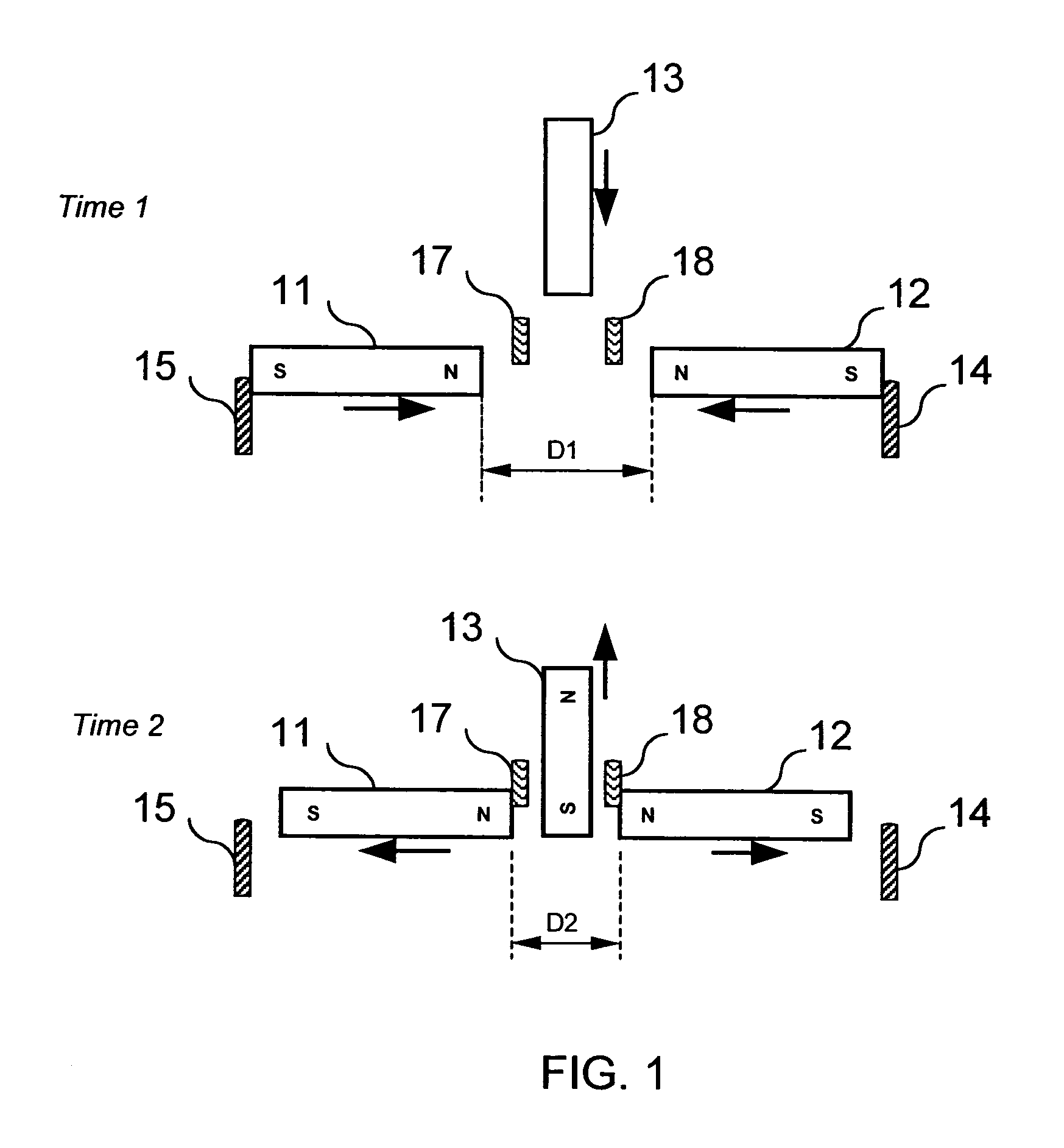
[0022]Referring to the drawings, in particular to FIG. 1 wherein a magnetic switch according to the first preferred embodiment of the invention is illustrated. The switch includes two coupled magnets 11 and 12 that are aligned with the like poles facing to each other resulting in a repelling force driving the coupled magnets apart. In this embodiment, the magnets 11 and 12 repel each other until they reach a dynamic equilibrium supported by the optional mechanical stops 14 and 15 as illustrated in the state of time 1 in FIG. 1. The magnets 11 and 12 may be pushed toward one another by applying an external force along the length of the magnets toward the center point between the magnets.

[0023]For the purpose of this invention, a third member 13 is inserted between the coupled magnets 11 and 12 as a magnetic field modifier to alter the repelling force between the magnets into two attracting forces. The magnetic field modifier 13 in the illustrated example is a magnetizable metal sheet...


PUM

PropertyMeasurementUnit
magnetic fieldaaaaaaaaaa
displacementaaaaaaaaaa
magneticaaaaaaaaaa

Abstract

A magnetic field based mechanical apparatus is disclosed. The apparatus is based on coupled attracting or opposing magnets in conjunction with the insertion or removal of a magnetic field modifier. In the preferred embodiment, two repelling magnets are drawn together with the insertion of a magnetic field modifier. The field modifier may be another magnet having an opposing pole. Removal of the field modifier returns the forces to their original states. This oscillating motion may be driven with a low energy and/or small power supply. The resulting motion of the opposing magnets can drive mechanical system such as a linear, gear, ratchet, or reciprocating drive.

Description

CROSS-REFERENCE TO RELATED APPLICATIONS[0001]This application is a Continuation-in-Part of the U.S. patent application Ser. No. 10 / 472,856 filed on 18 Sep. 2003 and claims priority to the U.S. Provisional Patent Application Ser. No. 60 / 500,382 filed on 5 Sep. 2003, and is related to U.S. Pat. No. 6,152,876, U.S. Pat. No. 6,040,578, and U.S. Provisional Patent Application 60 / 448,840 filed on 19 Feb. 2003, the contents of all of which are incorporated by reference herein by the reference thereto.BACKGROUND OF THE INVENTION[0002]1. The Field of the Invention[0003]This invention generally relates to magneto-mechanical devices. More particularly, the invention relates to a magneto-mechanical apparatus with a magnetic field modifier that, when inserted into or removed from the magnetic field between two magnet components of the apparatus, triggers a displacement of at least one of the magnet components, which is coupled to a drive or a switch.[0004]2. Description of the Related Arts[0005]...

Claims


Application Information

Patent Timeline
Patent Type & Authority Patents(United States)
IPC IPC(8): H01F7/20H01H9/00A61B5/00F04B9/02F04B17/00G01N21/35G01N21/49H01FH01F7/02H01H36/00H02K99/00
CPCF04B9/02H01H36/0073F04B17/00A61B5/14532G01N21/49H01H3/34
Inventor KINCAID, STEPHENACOSTA, GEORGE M.ABUL-HAJ, ROXANNEHAZEN, KEVIN H.
Owner GLT ACQUISITION
Why Eureka
Try Eureka