Method Of Treating Volatile Organic Compound And System For Treating Volatile Organic Compound Using Gas Turbine

a technology of volatile organic compound and treatment method, which is applied in the direction of machines/engines, combustion types, lighting and heating apparatus, etc., can solve the problems of increasing the cost of operating the facility, and achieve the reduction of the amount of nox in the combustion gas discharged from the gas turbine, the effect of improving overall energy efficiency and suppressing the effect of nox

Active Publication Date: 2008-02-21
IHI POWER SYST CO LTD
View PDF12 Cites 4 Cited by
  • Summary
  • Abstract
  • Description
  • Claims
  • Application Information

AI Technical Summary

Benefits of technology

[0031] In the present invention, since the steam mixed with the volatile organic compound is supplied to the combustion chamber of the gas turbine and combusted, the volatile organic compound can be made harmless. Moreover, the situation where highly concentrated volatile organic compound is supplied to the combustion chamber so that the flame temperature becomes too high can be prevented, and the overall energy efficiency can be improved. Furthermore, by supplying the steam to the combustion chamber, the amount of NOx in the combustion gas discharged from the gas turbine can be reduced, and hence deterioration in the surroundings due to the NOx can be suppressed.
[0032] Moreover, by producing steam using heat retained in the combustion gas discharged from the gas turbine, and supplying this to the adsorption apparatus, then compared to the case where the steam is provided from another system, the energy necessary for producing the steam can be reduced.

Problems solved by technology

Finally, the volatile organic compound which has been separated from the water is burnt, and thus decomposed.
In the conventional treatment method, in addition to the cost required for the set up of the treatment facility, there is also an increase in cost necessary for operating the facility.

Method used


Image

  • Method Of Treating Volatile Organic Compound And System For Treating Volatile Organic Compound Using Gas Turbine
  • Method Of Treating Volatile Organic Compound And System For Treating Volatile Organic Compound Using Gas Turbine
  • Method Of Treating Volatile Organic Compound And System For Treating Volatile Organic Compound Using Gas Turbine

Examples


first embodiment

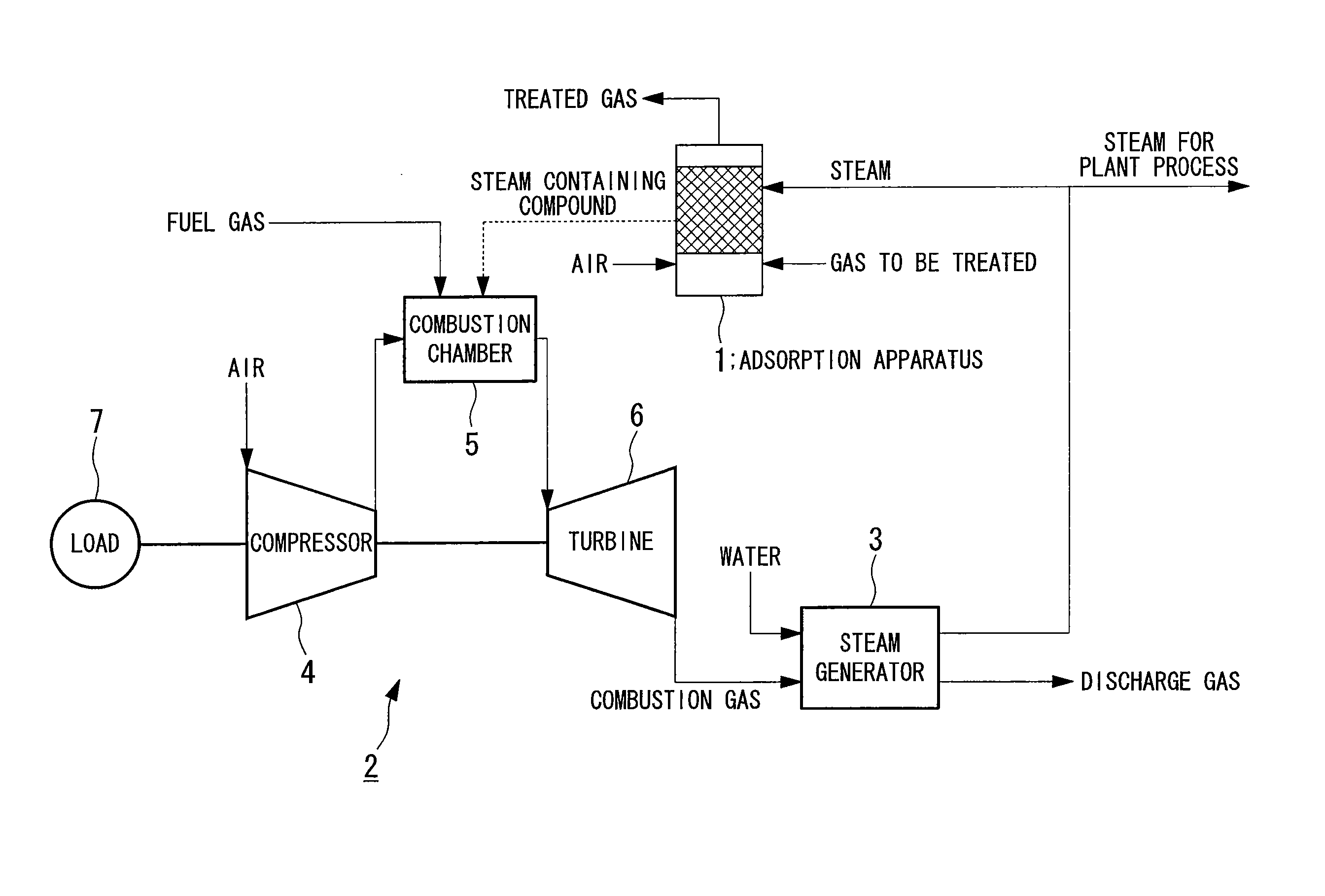
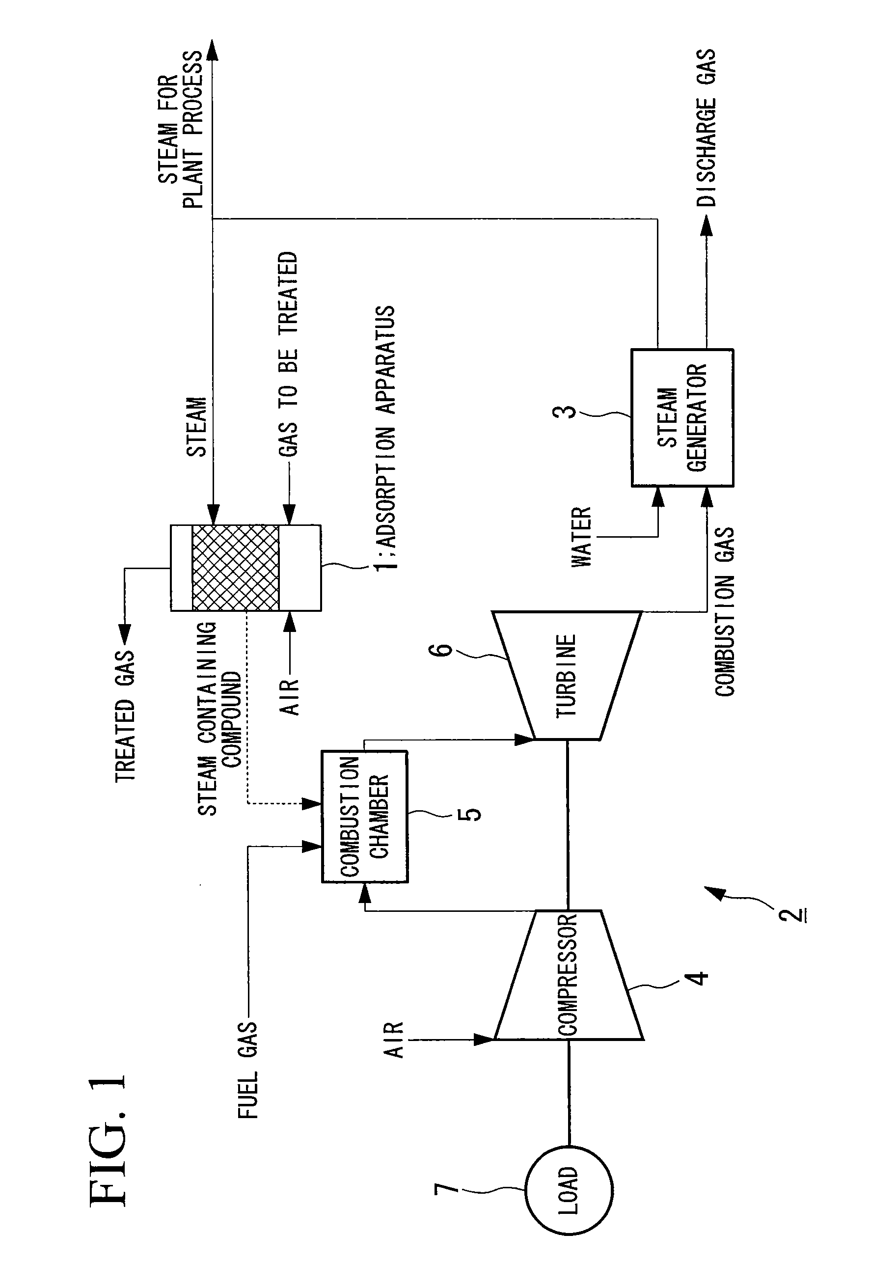
[0049]FIG. 1 is a system block diagram showing a characteristic configuration of a volatile organic compound treatment system according to a first embodiment of the present invention. In FIG. 1, reference symbol 1 denotes an adsorption apparatus, 2 denotes a gas turbine, and 3 denotes a steam generator.

[0050] The adsorption apparatus 1 adsorbs a volatile organic compound contained in a gas to be treated, in an adsorbent thereinside, to thereby remove the volatile organic compound from the gas to be treated, and desorbs the volatile organic compound adsorbed in the adsorbent, using steam under a pressurized environment, and mixes this with steam. For the adsorbent, for example activated carbon is used. Furthermore, the pressurized environment is realized by supplying steam to the adsorption apparatus 1.

[0051] In such an adsorption apparatus 1, the gas to be treated is input from the outside, and together with this, steam is input from the steam generator 3. On the other hand, the t...

second embodiment

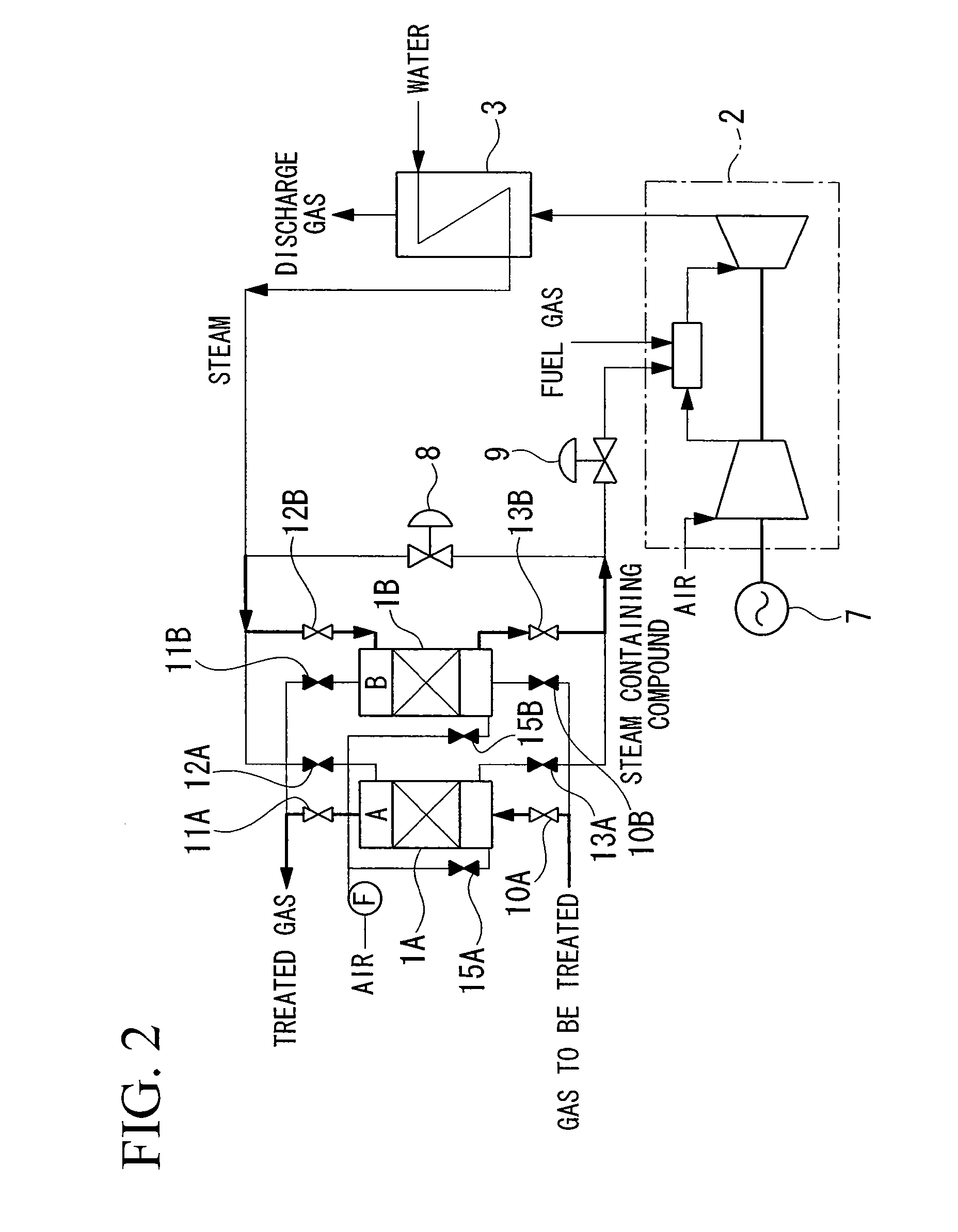
[0060] Next is a description of a second embodiment of the present invention, with reference to the system block diagram shown in FIG. 2.

[0061] At first, the quantity of steam that the gas turbine (i.e. the combustion chamber 5) requires for its own drive (the combustion steam quantity), and the quantity of steam that the adsorption apparatus 1 requires for adsorbing the volatile organic compound (the compound adsorption steam quantity), are not necessarily the same. That is, the combustion steam quantity needs to be determined from the requirements for safe and efficient operation of the gas turbine, while the compound adsorption steam quantity needs to be determined from the requirement for effective adsorption of the volatile organic compound.

[0062] In the volatile organic compound treatment system according to the first embodiment, the configuration was such that the steam containing compound discharged from the adsorption apparatus 1 was supplied as is, to the combustion cham...

third embodiment

[0084] Next is a description of a third embodiment of the present invention, with reference to FIG. 6.

[0085] The third embodiment is one which applies pretreatment to the gas to be treated in order to improve the treatment efficiency. FIG. 6 is a system block diagram of a volatile organic compound treatment system according to the third embodiment. Components the same as for the volatile organic compound treatment system according to the first and second embodiments, are denoted by the same reference symbols.

[0086] In FIG. 6, reference symbol 16 denotes a dehumidifying tower, 17 and 20 denote chillers, 18 denotes a concentrator, and 19 denotes a fan. The dehumidifying tower 16 is a tower which dehumidifies the gas to be treated by gas / liquid contact with cold water. That is to say, the dehumidifying tower 16 is constructed so that gas to be treated is supplied from below, and the gas to be treated is discharged from above, while cold water is watered from above to below. Consequen...


PUM


Abstract

The invention aims at making a volatile organic compound harmless, and in addition comprehensively improving the energy efficiency within a facility where treatment of the volatile organic compound is necessary. In the invention, in order to achieve this aim, a solution means is adopted where, a discharge gas containing a volatile organic compound is supplied to an adsorption apparatus to adsorb the volatile organic compound in an adsorbent. The volatile organic compound is desorbed from the adsorbent with pressurized steam and mixed with the steam. The steam containing the volatile organic compound is supplied, in the pressurized state, to the combustion chamber of a gas turbine, and burned together with a fuel gas.

Description

TECHNICAL FIELD [0001] The present invention relates to a treatment method and a treatment system for treating a gaseous volatile organic compound using a gas turbine. BACKGROUND ART [0002] In the case of using various types of volatile organic compounds such as toluene, xylene, or the like, there is much concern regarding disposal of the volatile organic compound after use. In the case where the release is small, the discharge gas containing the used volatile organic compounds may be discharged to the atmosphere within a range which falls below a reference value. However in the case where the discharge amount is large (that is in most cases), this is treated by providing a separate treatment facility. [0003] As a conventional general treatment method, at first the discharge gas containing the volatile organic compound is supplied to an adsorption apparatus, and the volatile organic compound is adsorbed in an adsorbent, and the adsorbent which has adsorbed the volatile organic compo...

Claims


Application Information

Patent Timeline
Patent Type & Authority Applications(United States)
IPC IPC(8): F02C3/20F02C3/30F23G7/06
CPCF01K17/04F02C3/22F02C6/18F23G5/02F23G5/46F23G7/065Y02E20/12F23G2201/60F23G2206/202F23G2206/203F23G2209/14F23L7/005F23G7/066Y02A50/20F23G7/06F02C3/30
Inventor UJI, SHIGEKAZU
Owner IHI POWER SYST CO LTD
Why Eureka
Try Eureka