Molten salt battery device and control method for molten salt battery device

a technology of molten salt battery and control method, which is applied in the direction of secondary cells, electrochemical generators, batteries, etc., can solve the problems of difficulty in supplying energy from the outside, molten salt battery device of non-fixed type has a certain amount of time to heat molten, and the molten salt battery itself is not allowed to serve as a power supply, etc., to achieve the effect of increasing the capacity, improving the efficiency of energy utilization, and increasing the warm

Inactive Publication Date: 2014-09-18
SUMITOMO ELECTRIC IND LTD
View PDF1 Cites 5 Cited by
  • Summary
  • Abstract
  • Description
  • Claims
  • Application Information

AI Technical Summary

Benefits of technology

[0007]Further, a certain amount of time is necessary for heating the molten salt battery to a temperature at which the molten salt battery is allowed to operate. Thus, a warm-up time occurs until the molten salt battery device becomes usable at the time of startup. In particular, when the size of the molten salt battery is increased for the purpose of increasing the capacity, a problem arises that the warm-up time increases. Further, for the purpose of improving the efficiency of energy utilization, energy consumption for heating the molten salt battery need be reduced.
[0008]The present invention has been devised in view of such situations. An object thereof is to provide: a molten salt battery device in which the molten salt battery is heated easily and the warm-up time at the time of startup is reduced so that energy necessary for heating the molten salt battery is reduced; and a control method for molten salt battery device.

Problems solved by technology

Nevertheless, at the time of startup, the molten salt battery itself is not allowed to serve as a power supply for the heater.
In particular, the molten salt battery device of non-fixed type has a problem of difficulty in supplying energy from the outside for the purpose of heating the molten salt battery.
Further, a certain amount of time is necessary for heating the molten salt battery to a temperature at which the molten salt battery is allowed to operate.
In particular, when the size of the molten salt battery is increased for the purpose of increasing the capacity, a problem arises that the warm-up time increases.

Method used


Image

  • Molten salt battery device and control method for molten salt battery device
  • Molten salt battery device and control method for molten salt battery device
  • Molten salt battery device and control method for molten salt battery device

Examples


embodiment 1

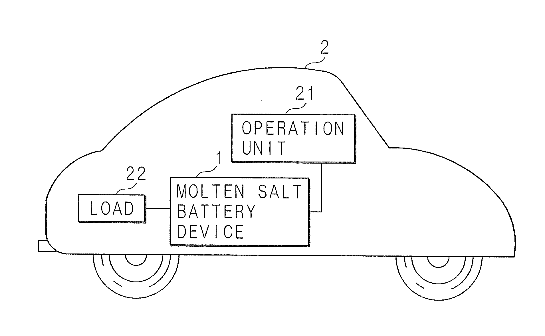
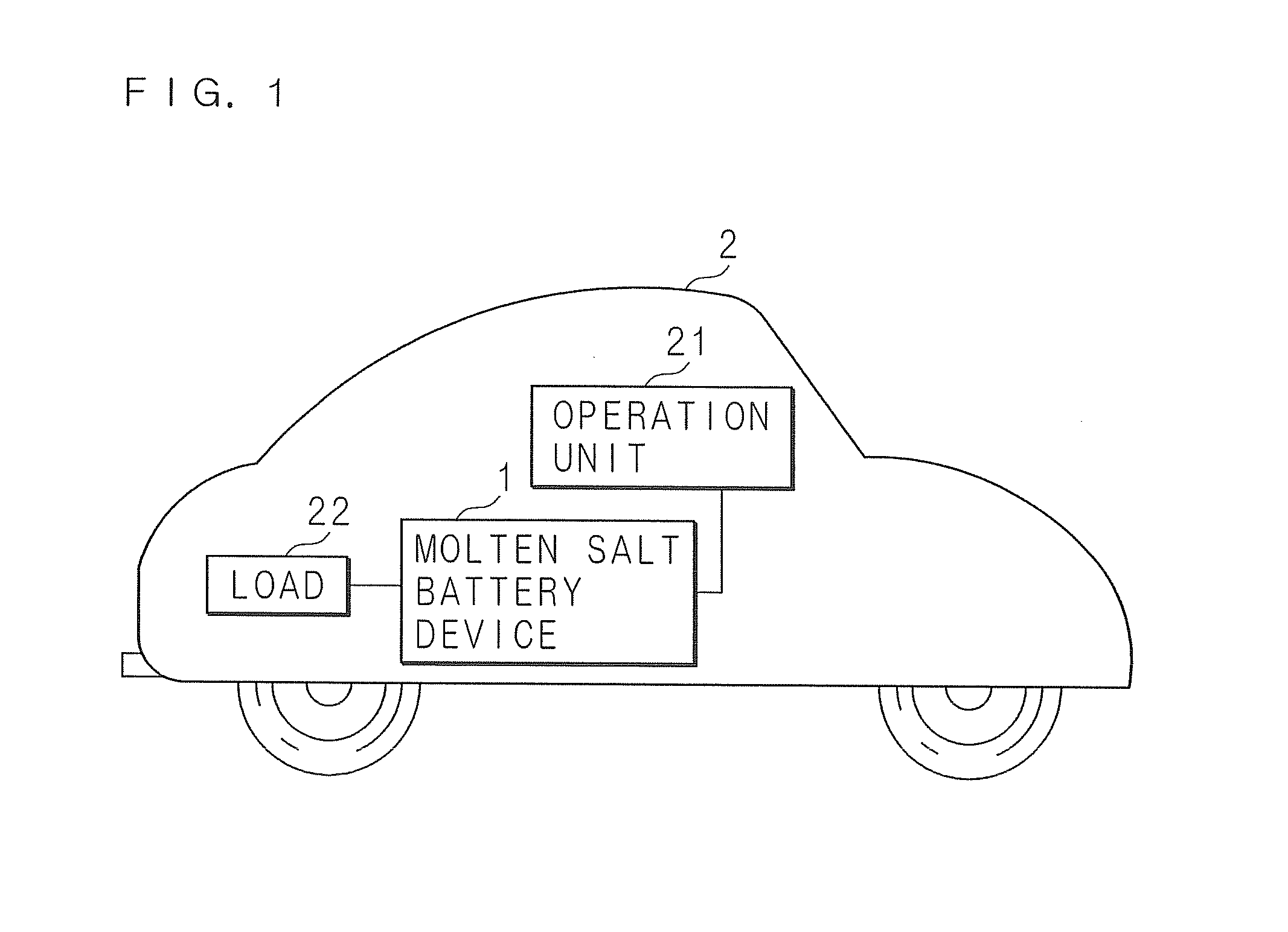
[0037]FIG. 1 is a schematic diagram illustrating a mode of utilization of a molten salt battery device according to Embodiment 1. The molten salt battery device 1 is an electric power storage device of car-mounted type and is mounted on an automobile 2. For example, the automobile 2 is an electric car or a hybrid car. The molten salt battery device 1 is connected through a signal line to an operation unit 21 operated by a user for inputting an instruction such as an instruction of operation start. Further, the molten salt battery device 1 is connected through a power line to a load 22 such as a motor mounted on the automobile 2.

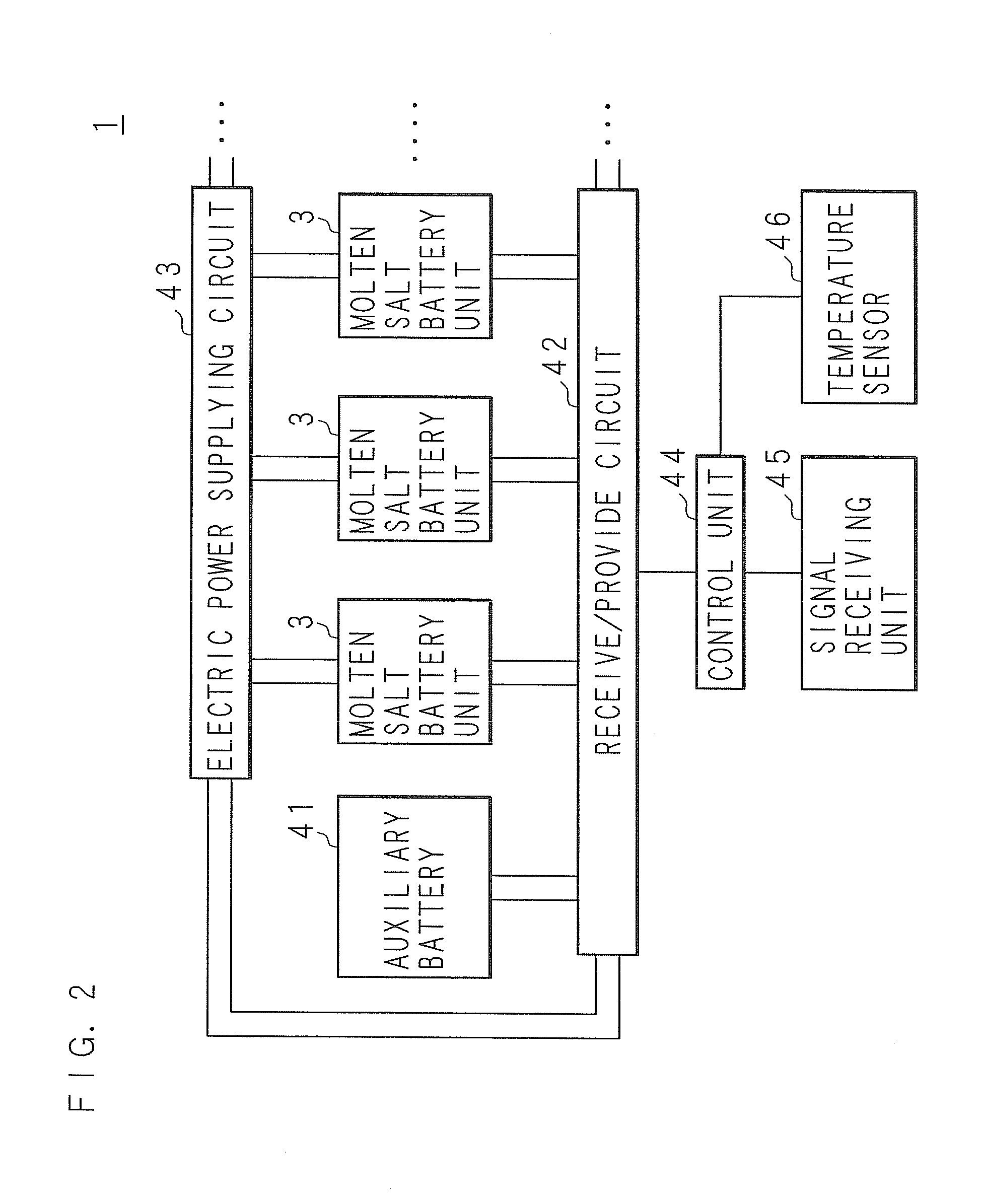
[0038]FIG. 2 is a block diagram illustrating the electrical configuration of the molten salt battery device 1 according to Embodiment 1. The molten salt battery device 1 includes: a plurality of molten salt battery units 3, 3 . . . ; and an auxiliary battery 41 capable of operating at room temperature. The plurality of molten salt battery units 3, 3 . . . and...

embodiment 2

[0058]FIG. 5 is a block diagram illustrating the electrical configuration of a molten salt battery device 1 according to Embodiment 2. In Embodiment 2, the molten salt battery device 1 includes a capacitor 5 in place of the auxiliary battery 41 in Embodiment 1. The capacitor 5 is connected to the receive / provide circuit 42 through a power line. Then, the capacitor 5 supplies electric power to one molten salt battery unit 3 through the receive / provide circuit 42 and the electric power supplying circuit 43. The receive / provide circuit 42 is allowed to receive electric power from the load 22 or an external electric power source (not illustrated) and then charge the capacitor 5 with the supplied electric power. Further, the receive / provide circuit 42 adjusts the current and the voltage discharged from the capacitor 5, and is allowed to provide the electric power from the capacitor 5, to the load 22 in the outside of the molten salt battery device 1. Further, the control unit 44 is conne...

embodiment 3

[0069]Embodiments 1 and 2 have been described for a mode that the molten salt battery device 1 is of non-fixed type. In Embodiment 3 is described for a mode of fixed type. FIG. 7 is a block diagram illustrating the electrical configuration of a molten salt battery device 1 according to Embodiment 3. In Embodiment 3, the molten salt battery device 1 does not include the auxiliary battery 41 in Embodiment 1. Further, the receive / provide circuit 42 is connected to an external electric power source 47 such as a commercial electric power source separately from the external load. The receive / provide circuit 42 supplies the electric power provided from the external electric power source 47 to the electric power supplying circuit 43. Then, the electric power supplying circuit 43 supplies the supplied electric power to one molten salt battery unit 3. In the present embodiment, the external electric power source 47 serves as an electric power source in the present invention. The other points ...


PUM

PropertyMeasurementUnit
temperatureaaaaaaaaaa
electric poweraaaaaaaaaa

Abstract

A molten salt battery device includes: a plurality of molten salt battery units; and an auxiliary battery (an electric power source) capable of operating at room temperature. Each molten salt battery unit includes a heater. At the time of startup, the auxiliary battery supplies electric power to the heater of one molten salt battery unit so that the one molten salt battery unit is heated by the heater and thereby allowed to operate. The one molten salt battery unit allowed to operate supplies electric power to the heaters of the other molten salt battery units so that the other molten salt battery units are heated by the heaters and thereby allowed to operate. The molten salt battery is easily heated without the necessity of a large amount of energy and hence the molten salt battery device starts up in a short time.

Description

[0001]This application is the national phase under 35 U.S.C. §371 of PCT International Application No. PCT / JP2012 / 077396 which has an International filing date of Oct. 24, 2012 and designated the United States of America.BACKGROUND[0002]1. Technical Field[0003]The present invention relates to: a molten salt battery device provided with a plurality of molten salt batteries; and a control method of operating the molten salt batteries.[0004]2. Description of Related Art[0005]For the purpose of efficient utilization of electric power, batteries having a high energy density and a high efficiency are required. As a battery of such kind, a sodium-sulfur battery disclosed in Japanese Patent Application Laid-Open No. 2007-273297 has been developed. Another example of a battery having a high energy density and a high efficiency is a molten salt battery. The molten salt battery is a battery employing molten salt as electrolyte and operates in a state that the molten salt has been melted. Emplo...

Claims


Application Information

Patent Timeline
Patent Type & Authority Applications(United States)
IPC IPC(8): H01M10/39H01M10/615H02J7/00H01M10/46H01M10/44H01M10/60H01M10/625H01M10/633H01M10/647H01M10/6571H01M10/658
CPCH01M10/399H01M10/5006H01M10/5016H01M10/5032H01M10/5081H02J7/0052H01M10/39H01M10/44H01M10/46H01M2220/20H01M2300/0048H01M10/5087H01M10/441H01M16/00H01M10/625H01M10/615H01M10/657H01M10/647H01M10/658Y02E60/10H01M10/63H01M10/48H02J7/00
Inventor KOBAYASHI, EIICHISAKA, HIRONOBU
Owner SUMITOMO ELECTRIC IND LTD
Why Eureka
Try Eureka