Magnetic Field Generator

a generator and magnetic field technology, applied in the field of magnetic field generators, can solve the problems of inefficient transfer of inability to create inability to efficiently transfer heat generated by the surface heater, so as to achieve the effect of generating a uniform magnetic field of a desired intensity, delivering heat more quickly and efficiently, and facilitating heat conductance to the permanent magnet group

Inactive Publication Date: 2008-12-11
HITACHI METALS LTD
View PDF18 Cites 3 Cited by
  • Summary
  • Abstract
  • Description
  • Claims
  • Application Information

AI Technical Summary

Benefits of technology

[0021]Preferably, the magnetic field generator includes a heat conducting member provided on at least part of a surface of the second permanent magnet group. By providing a heat conducting member also on the surface of the second permanent magnet group as described, heat generated by the heating means is conducted more uniformly and quickly to the second permanent magnet group. Therefore, it becomes possible to generate a uniform magnetic field of a desired intensity more stably.
[0022]Further preferably, heating means is buried in the heat conducting member. By burying a heating means in the heat conducting member, heat generated by the heating means is conducted to the heat conducting member without diffusing to the outside, and therefore it becomes possible to deliver heat more quickly and efficiently to the permanent magnet group. Further, since heat is conducted to the permanent magnet group more easily, it becomes possible to further reduce energy necessary to drive the heating means and to reduce running cost.
[0023]Further preferably, the magnetic field generator includes a coating material formed on at least part of the permanent magnets and having a thermal conductivity not lower than 150 W / m·K. By forming a coating material on the permanent magnets as described, heat generated by the heating means is conducted more uniformly and quickly by the coating material to the permanent magnets and thus to the permanent magnet group. Therefore, it becomes possible to generate a uniform magnetic field of a desired intensity more stably.
[0024]Further preferably, the magnetic field generator includes a temperature sensor disposed near the heating means. By disposing a temperature sensor near the heating means as described, it becomes possible to sense the heat generated by the heating means quickly and to prevent the heating means from generating an unnecessary amount of heat. In particular, when the heating means is disposed in or near a permanent magnet group, thermal demagnetization can occur in the permanent magnets if the amount of heat generated by the heating means becomes excessively large. However, this can be prevented by placing a temperature sensor near the heating means.
[0025]Further preferably, the magnetic field generator includes a heat insulation material which covers the permanent magnet group. By covering the permanent magnet group with a heat insulation material as described, temperature change in the permanent magnet group caused by changes in the ambient temperature is reduced. Therefore, it becomes possible to maintain the permanent magnet group at a constant temperature more stably. Further, since heat diffusion from the permanent magnet group to the outside becomes less, and the temperature decrease of the permanent magnet group becomes less, it becomes possible to further reduce energy necessary to drive the heating means and to reduce running cost. The heat insulation material is suitably provided by, for example, a vacuum insulation material in the form of a vacuum pack of a core material made of inorganic fiber heat insulation material such as glass wool or foamed plastic heat insulation material such as foamed polystyrene and foamed urethane into a package made of a metal film, etc. which has a good gas insulation capability.
[0026]Further preferably, the magnetic field generator includes a heat storage member which covers the permanent magnet group. In this case, the heat storage member holds the heat of the permanent magnet group, and when the temperature of the permanent magnet group decreases, heat held in the heat storage member is conducted to the permanent magnet group. Therefore, it is possible to maintain the permanent magnet group at a constant temperature more stably. Further, since the heat is conducted from the heat storage member to the permanent magnet group when the temperature of the permanent magnet group decreases, it becomes possible to further reduce energy necessary to drive the heating means and to reduce running cost. Heat storage material included in the heat storage member is suitably provided by an inorganic hydrated salt which has a large heat storage capacity and can hold heat stably.

Problems solved by technology

In order to obtain clear tomographic images, the magnetic field generator 1 must be able to generate, within a magnetic field space 5 in its space, a magnetic field which has a uniformity accuracy within 1×10⁻⁴ (within 100 PPM) in a range of 0.02 T through 3.0 T. However, the permanent magnet group 4a recently is often made of Nd—Fe—B sintered magnets, which has a residual magnetic flux density temperature coefficient of −0.1% / ° C. approx: Magnetic characteristics change with temperature change, so it is difficult to create a uniform magnetic field of a desired intensity.
However, the technique according to Patent Document 1 poses a problem of complication in apparatuses related to temperature control since the air must be forced to move by the fan.
In addition, use of air as a heat transfer medium poses another problem that the heat generated by the surface heater is not transferred efficiently to the permanent magnet group 4a.
The techniques according to Patent Documents 2 and 3 also have the problem of inefficient transfer of heat generated by the surface heater, to the permanent magnet group 4a because the heat diffuses from a surface of the surface heater facing away from the surface that makes contact with the plate yoke 3.

Method used


Image

  • Magnetic Field Generator
  • Magnetic Field Generator
  • Magnetic Field Generator

Examples


Embodiment Construction

[0069]Hereinafter, embodiments of the present invention will be described with reference to the drawings.

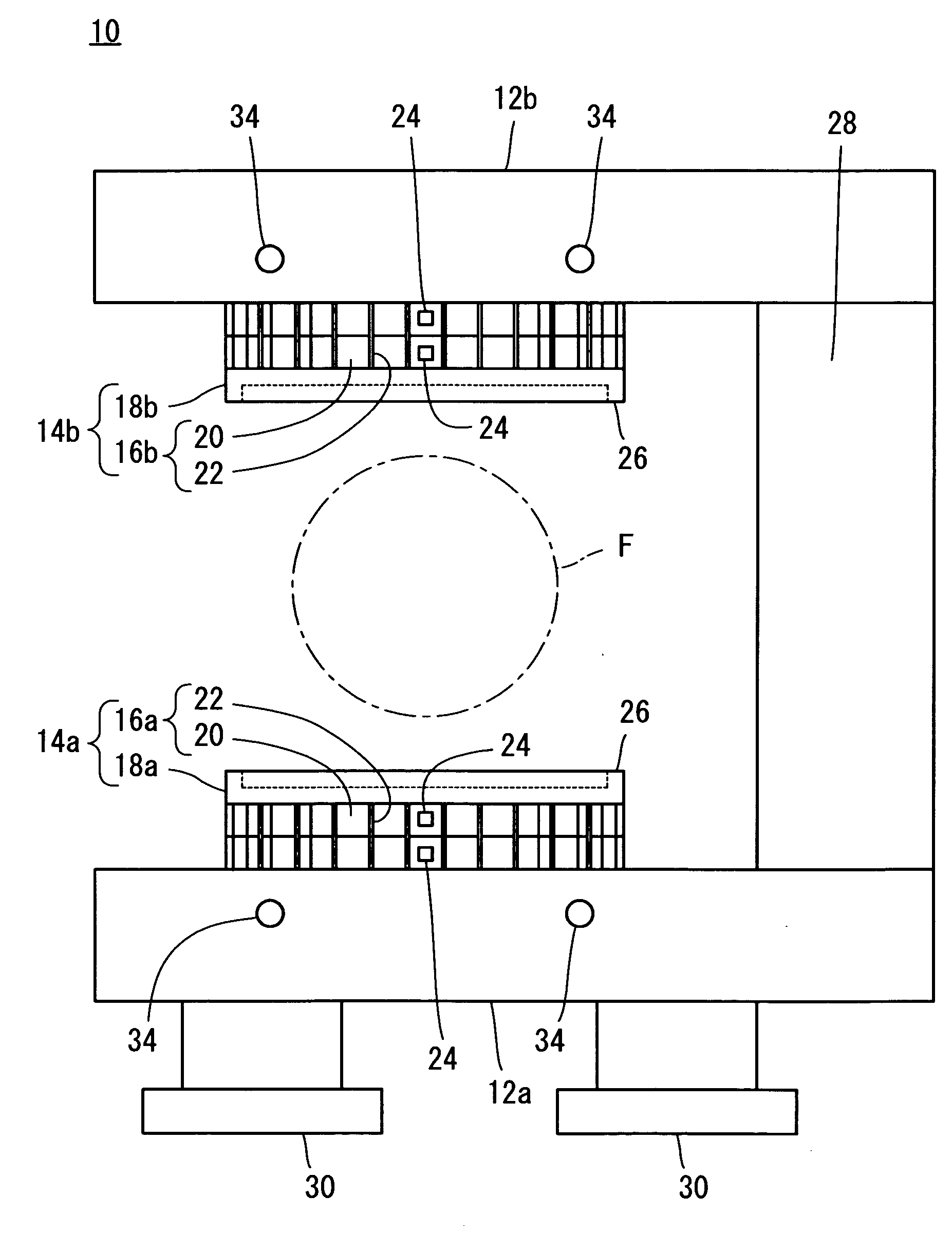
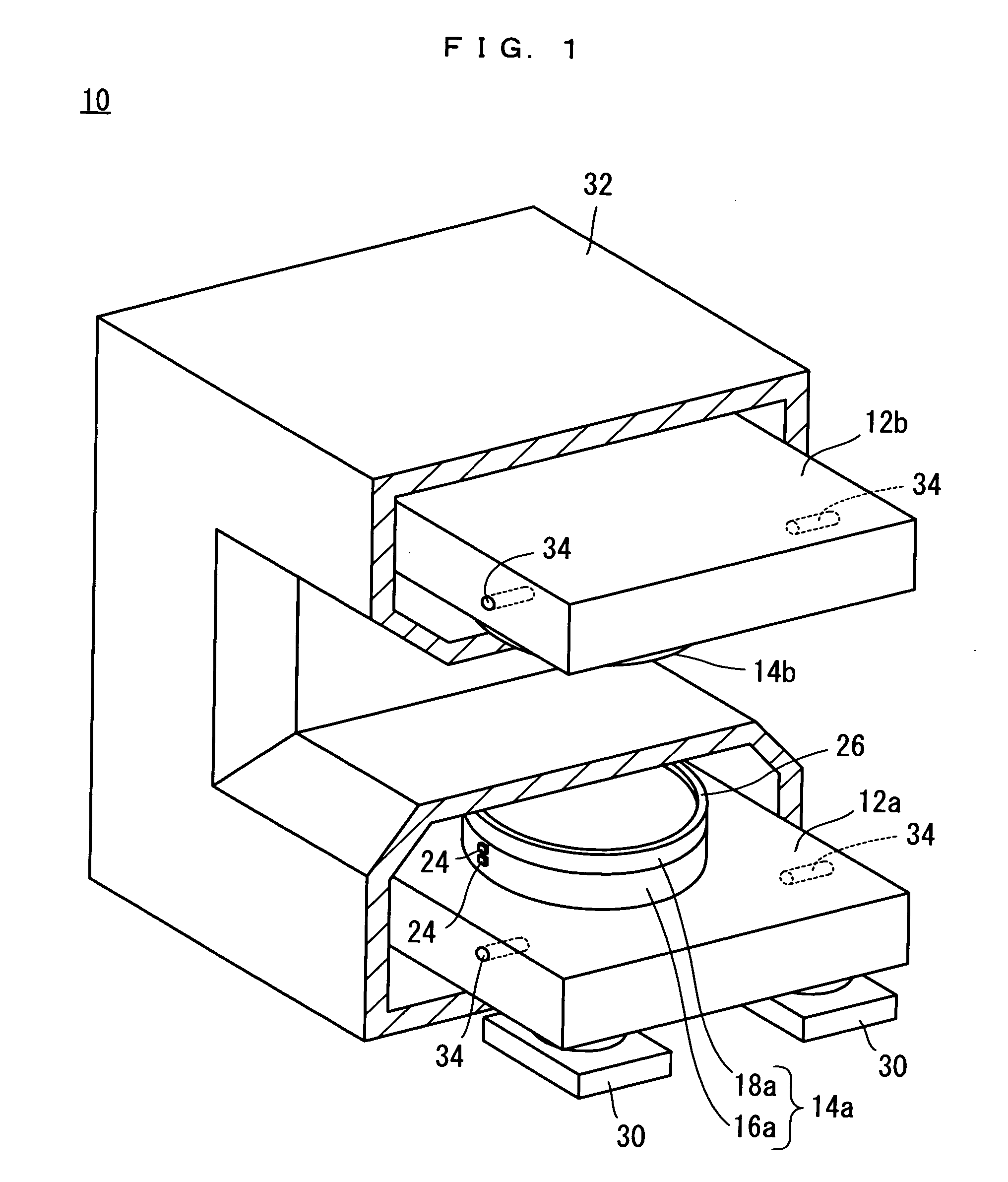
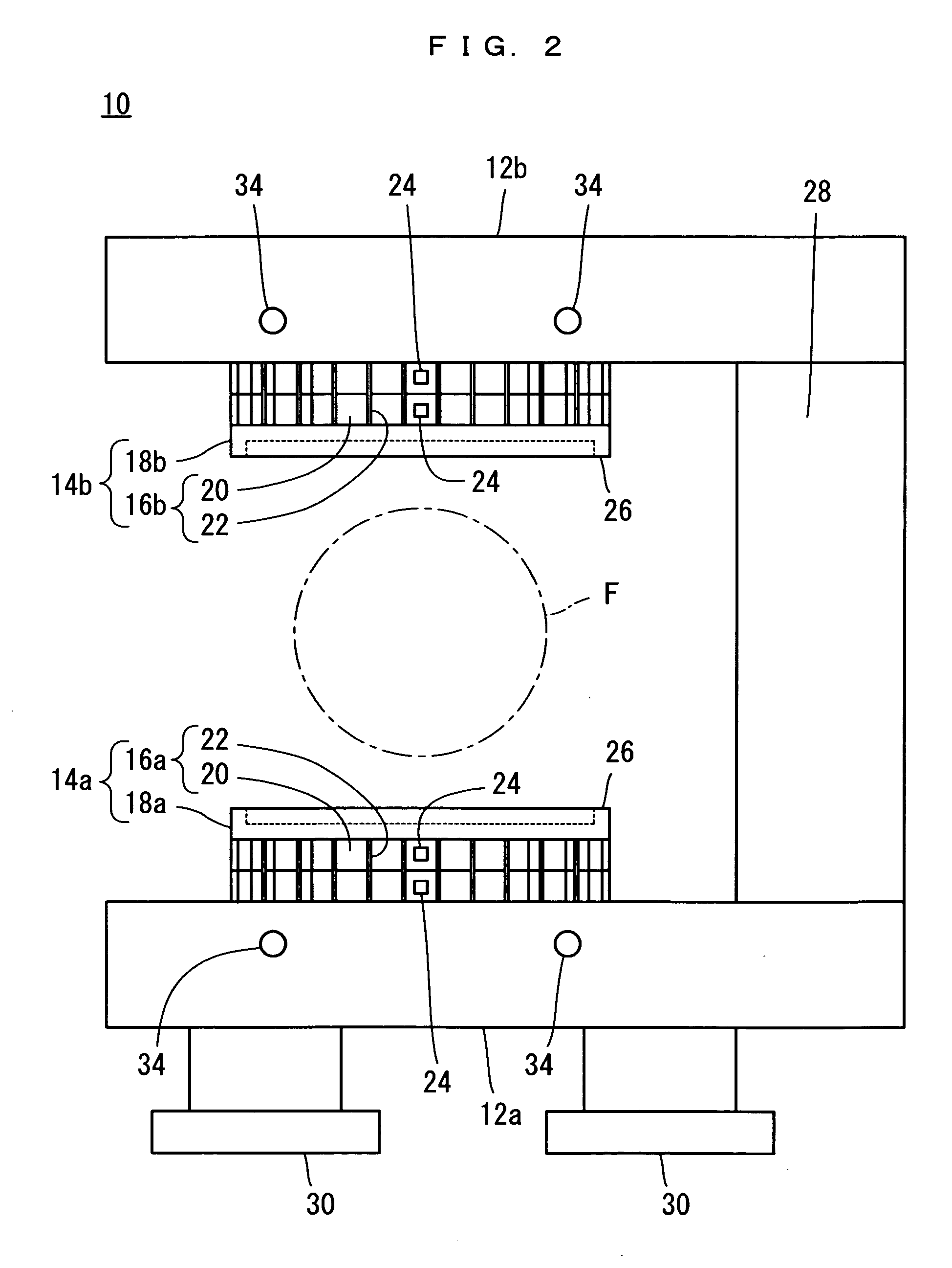
[0070]Referring to FIG. 1 and FIG. 2, a magnetic field generator 10 according to an embodiment of the present invention is a magnetic field generator for an open type MRI apparatus, and includes a pair of plate yokes 12a, 12b opposed to each other with a space in between and a pair of magnetic poles 14a, 14b.

[0071]The magnetic pole 14a includes a permanent magnet group 16a and a pole piece 18a. Likewise, the magnetic pole 14b includes a permanent magnet group 16b and a pole piece 18b. The permanent magnet group 16a is fixed on a surface which is faced to the plate yoke 12b, of the plate yoke 12a. Likewise, the permanent magnet group 16b is fixed on a surface which is faced to the plate yoke 12a, of the plate yoke 12b. The pole piece 18a is fixed on a surface which is faced to the permanent magnet group 16b, of the permanent magnet group 16a. Likewise, the pole piece 18b is fixed...


PUM


Abstract

There is provided a magnetic field generator 10 which is capable of generating a uniform magnetic field of a desired intensity easily and stably without increasing running cost. The magnetic field generator 10 includes a pair of plate yokes 12a, 12b. The plate yokes 12a, 12b have opposed surfaces provided with magnetic pole 14a, 14b respectively. The magnetic pole 14a includes a permanent magnet group 16a whereas the magnetic pole 14b includes a permanent magnet group 16b. Each of the permanent magnet groups 16a, 16b is formed substantially in a disc like shape, as an integral body made of a plurality of permanent magnets 20 and a plurality of heat conducting members 22. Tubular heaters 34, buried in the plate yokes 12a, 12b, generate heat, which is conducted via the plate yokes 12a, 12b to each permanent magnet 20 and each heat conducting member 22 which constitute the permanent magnet groups 16a, 16b.

Description

TECHNICAL FIELD[0001]The present invention relates to magnetic field generators, and more specifically to permanent magnet type magnetic field generators used in MRI (Magnetic Resonance Imaging) apparatuses, etc.BACKGROUND ART[0002]Conventionally, MRI apparatuses, etc. are known as an apparatus in which a specimen is placed in a magnetic field (static magnetic field) generated by a magnetic field generator and tomographic images of the specimen is obtained.[0003]FIG. 28 shows a magnetic field generator 1 as an example of the magnetic field generator used in an MRI apparatus. The magnetic field generator 1 includes a pair of plate yokes 3 which are connected with each other by four column yokes 2, to face each other with a space in between. The opposed surfaces of the plate yokes 3 are each provided with a magnetic pole 4. Each magnetic pole 4 includes a permanent magnet group 4a fixed on the opposed surface of the plate yoke 3 and a pole piece 4b fixed on an opposed surface of the p...

Claims


Application Information

Patent Timeline
Patent Type & Authority Applications(United States)
IPC IPC(8): G01R33/383
CPCA61B5/055G01R33/3802G01R33/3806G01R33/383
Inventor AOKI, MASAAKI
Owner HITACHI METALS LTD
Why Eureka
Try Eureka