Electronic appliance

a technology of electronic appliances and keyboards, applied in the direction of electric apparatus casings/cabinets/drawers, pulse techniques, instruments, etc., can solve the problems of difficult for users to input characters by using keyboards, time-consuming and troublesome input,

Inactive Publication Date: 2006-03-21
SHARP KK
View PDF5 Cites 47 Cited by
  • Summary
  • Abstract
  • Description
  • Claims
  • Application Information

AI Technical Summary

Benefits of technology

[0021]Structured as described above, this electronic appliance, like the one described immediately before, operates with a minimum displacement of the flexible connecting member even when the second casing is unfolded or rotated to 180° or further to 360° relative to the first casing. This helps make the hinge mechanism, and thus the electronic appliance as a while, compact.

Problems solved by technology

In either way, it takes time and trouble to input characters.
Characters can easily be input by use of a keyboard, but, where appliances need to be compact, it is not possible to secure on a surface of the appliances an ample area to provide a keyboard in.
This inevitably results in small keys and a narrow key-to-key pitch, and thus makes it difficult for the user to input characters by use of those keys.
However, the structure proposed in the aforementioned patent publication does not permit the appliance to be used from different directions.
Thus, when the appliance is used in the laterally elongate orientation, it is easy to use the keyboard, but it is difficult to perform selection / determination operations.
By contrast, when the appliance is used in the longitudinally elongate orientation, it is easy to perform selection / determination operations, but it is difficult to use the keyboard.
With this wiring method, however, as the number of leads increases, the shaft needs to be made thicker.
This, disadvantageously, makes the hinge mechanism as a whole unduly large.
When the FPC board becomes loose, it is prone to deteriorate by making frequent contact with members provided around.
This makes difficult to make the appliance compact.
However, in a case where the screen display portion is unfolded to, for example, over 180°, how to deal with the looseness of an FPC board when the screen display portion is folded poses a serious problem.

Method used


Image

  • Electronic appliance
  • Electronic appliance
  • Electronic appliance

Examples


Embodiment Construction

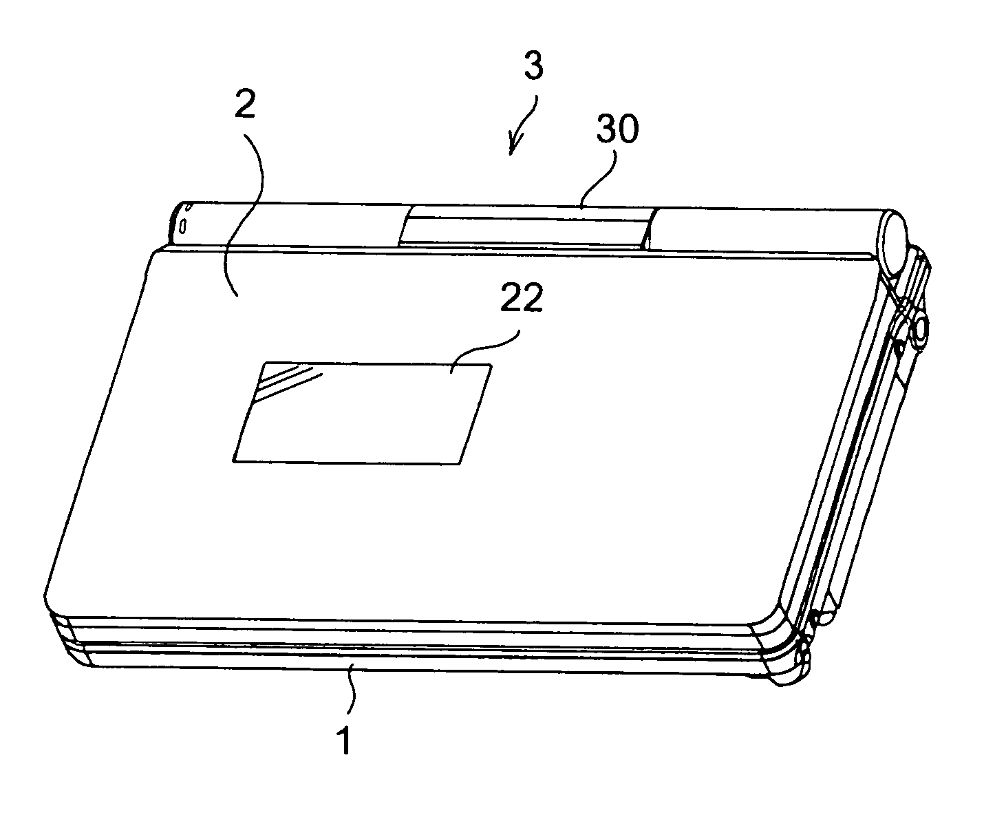
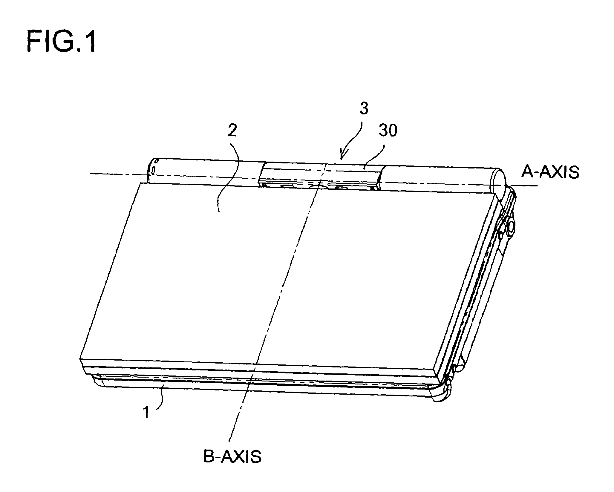
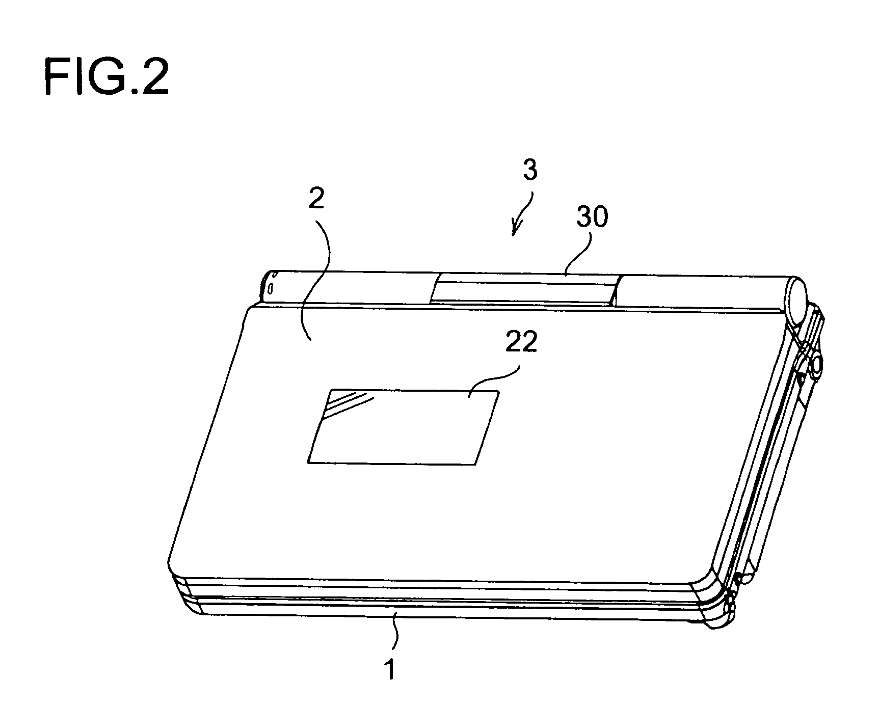
[0047]To achieve the first object, the inventors of the present invention have conducted an intensive study in search of a way of, in an electronic appliance in which a first casing provided with an input portion such as a keyboard and a second casing having a screen display portion provided on one face thereof are coupled together by a coupling, permitting easy input via the input portion and simultaneously permitting selection / decision operations to be performed easily with one hand as conventionally performed. The study has led the inventors to devise the present invention on the basis of the novel idea that the aim is attained by designing the appliance to be operable from different directions between when input is performed via the input portion and when input is performed by selection / decision operations.

[0048]Specifically, consider an appliance that is rectangular in shape as seen in a plan view with its first and second casings folded together. When input is performed via an...


PUM


Abstract

An electronic appliance includes a first casing having an input portion, a second casing having a screen display portion on one face thereof, a coupling, and a controller portion for controlling screen display on the screen display portion. The first and second casings are coupled together such that the electronic appliance can be moved between a first state, in which the second casing is unfolded relative to the first casing with the screen display portion pointing in the direction of the input portion, and a second state, in which the second casing is folded over the first casing with the face of the second casing opposite to the screen display portion facing the face of the first casing on which the input portion is provided. When the appliance changes between the first and second states, the controller portion rotates the screen display by 90° between the first and second states.

Description

CROSS-REFERENCE TO RELATED APPLICATION[0001]The present application claims priority under 35 U.S.C. §119 to Japanese Patent Application Nos. 2002-278563, filed Sep. 25, 2002; 2002-281090, filed Sep. 26, 2002; and 2002-351974 and 2002-352121, both filed Dec. 4, 2002, the entire disclosures of which are hereby incorporated by reference.BACKGROUND OF THE INVENTION[0002]1. Field of the Invention[0003]The present invention relates to an electronic appliance, and more particularly to an electronic appliance having two casings coupled together by a coupling.[0004]2. Description of the Prior Art[0005]In electronic appliances directed to mobile data processing, such as PDAs (personal digital assistants), the compactness of the appliances themselves counts most. Accordingly, in such appliances, compactness is achieved by providing operated members such as a jog dial and key tops, for example, around a display screen or on side faces of the appliances so that operations such as selection of or...

Claims


Application Information

Patent Timeline
Patent Type & Authority Patents(United States)
IPC IPC(8): G06F1/16
CPCG06F1/162G06F1/1677G06F1/165G06F2200/1614
Inventor TAKEMOTO, YOSHIKAZUNAGAI, KATSUHARU
Owner SHARP KK
Why Eureka
Try Eureka