
Fair multiplexing scheme for multiple input port router

Inactive Publication Date: 2006-03-21
CISCO TECH INC
View PDF19 Cites 17 Cited by
  • Summary
  • Abstract
  • Description
  • Claims
  • Application Information

AI Technical Summary

Benefits of technology

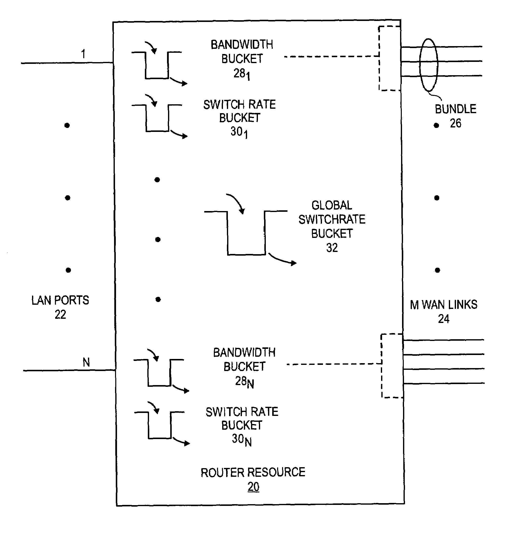
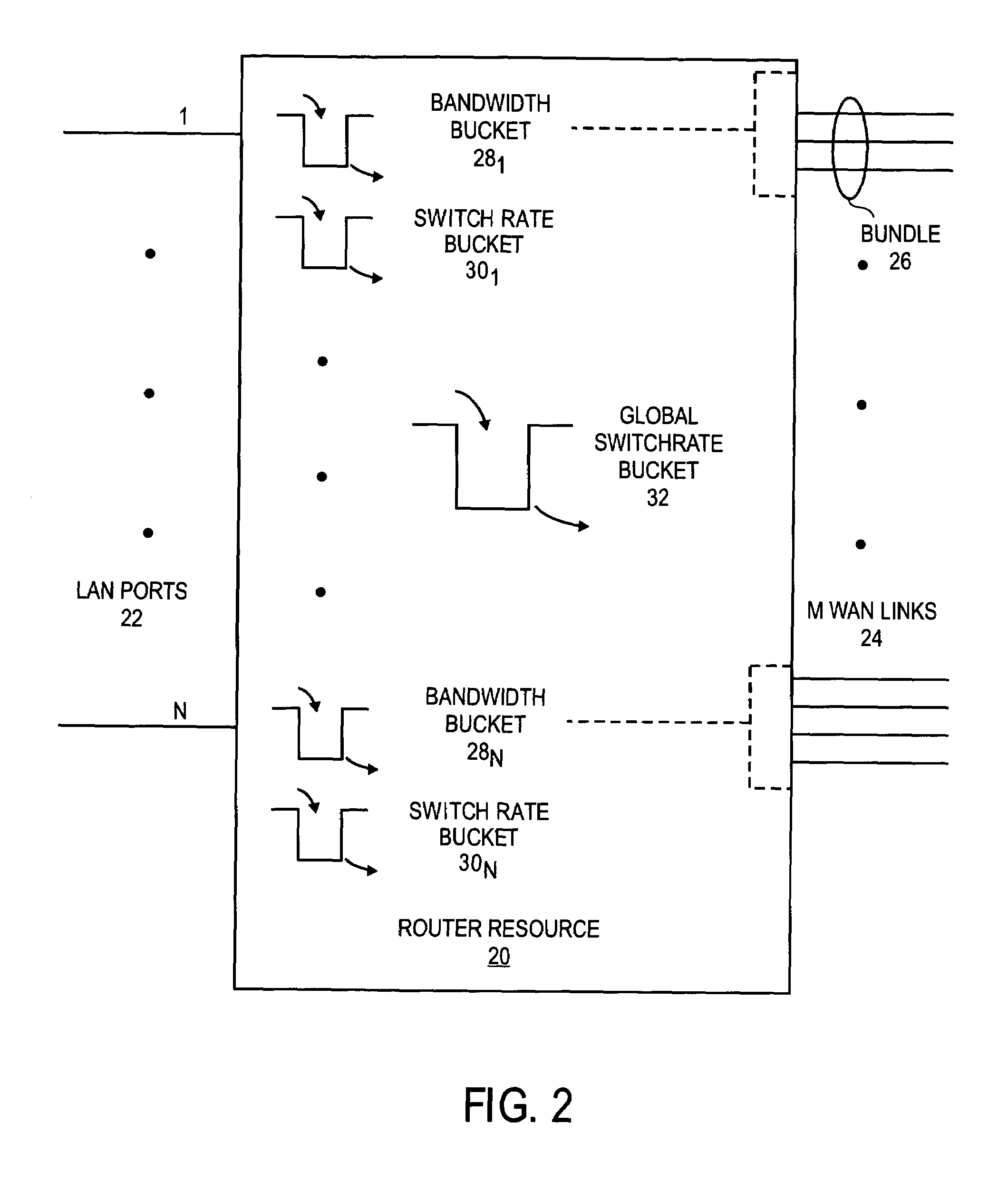
[0006]The present scheme provides a mechanism for preventing traffic from one (or a few) LAN ports of a router resource from dramatically affecting performance on other LAN ports thereof. In one embodiment, the utilization of a router resource at the interface between a first number of local area network ports and a second number of wide area network links by each LAN port is controlled according to the bandwidth availability of corresponding bundles of the WAN links assigned to each of the LAN ports and a switching capacity of the router resource. In this scheme, individual ones of the LANs ports may be permitted to exceed their fair share of the switching capacity of the router resource, but only if a current switching load due to the tra

Problems solved by technology

If the current switching load due to traffic from all of the LAN ports is equal to the maximum switching capacity of the router resource, however, then those of the LAN ports that are attempting to utilize more than their fair share of the bandwidth availability or the switching capacity may be throttled back.

Method used


Image

  • Fair multiplexing scheme for multiple input port router
  • Fair multiplexing scheme for multiple input port router
  • Fair multiplexing scheme for multiple input port router

Examples


Embodiment Construction

[0012]As indicated above, described herein is a scheme for controlling utilization of a router resource, which may be positioned at the interface between a number of LAN ports and a variety of WAN links. However, although this scheme will be described with reference to certain preferred embodiments, this description should not be read as limiting the more general applicability of the present invention, as expressed in the claims which follow. For example, the scheme may operate to control traffic bi-directionally. That is, traffic inbound on the WAN links may be controlled in a like manner. Also, the router resource may be any device configured as a router or not. Accordingly, the schemes described herein, and the test results presented therewith, should be regarded as exemplary, and not exclusionary.

[0013]The general solution provided by the present scheme can be discussed with reference to FIG. 2. As will become apparent, one advantage offered by the present scheme is that traffic...


PUM


Abstract

The present scheme provides a mechanism for preventing traffic on one ore more LAN ports from dramatically affecting performance on other LAN ports of a router resource. In one embodiment, the utilization of a router resource at the interface between a first number of local area network ports and a second number of wide area network links by each LAN port is controlled according to the bandwidth availability of corresponding bundles of the WAN links assigned to each of the LAN ports and a switching capacity of the router resource. In this scheme, individual ones of the LAN ports may be permitted to exceed their fair share of the switching capacity of the router resource, but only if a current switching load due to the traffic from all of the LAN ports is less than the maximum switching capacity for the router resource as a whole. If the current switching load due to traffic from all of the LAN ports is equal to the maximum switching capacity of the router resource, however, those of the LAN ports that are attempting to utilize more than their fair share of the bandwidth availability or the switching capacity may be throttled back. Such throttling back may include dropping packets inbound on those LAN ports that are attempting to utilize more than their fair share of the resources, preferably at the entry point to the router resource.

Description

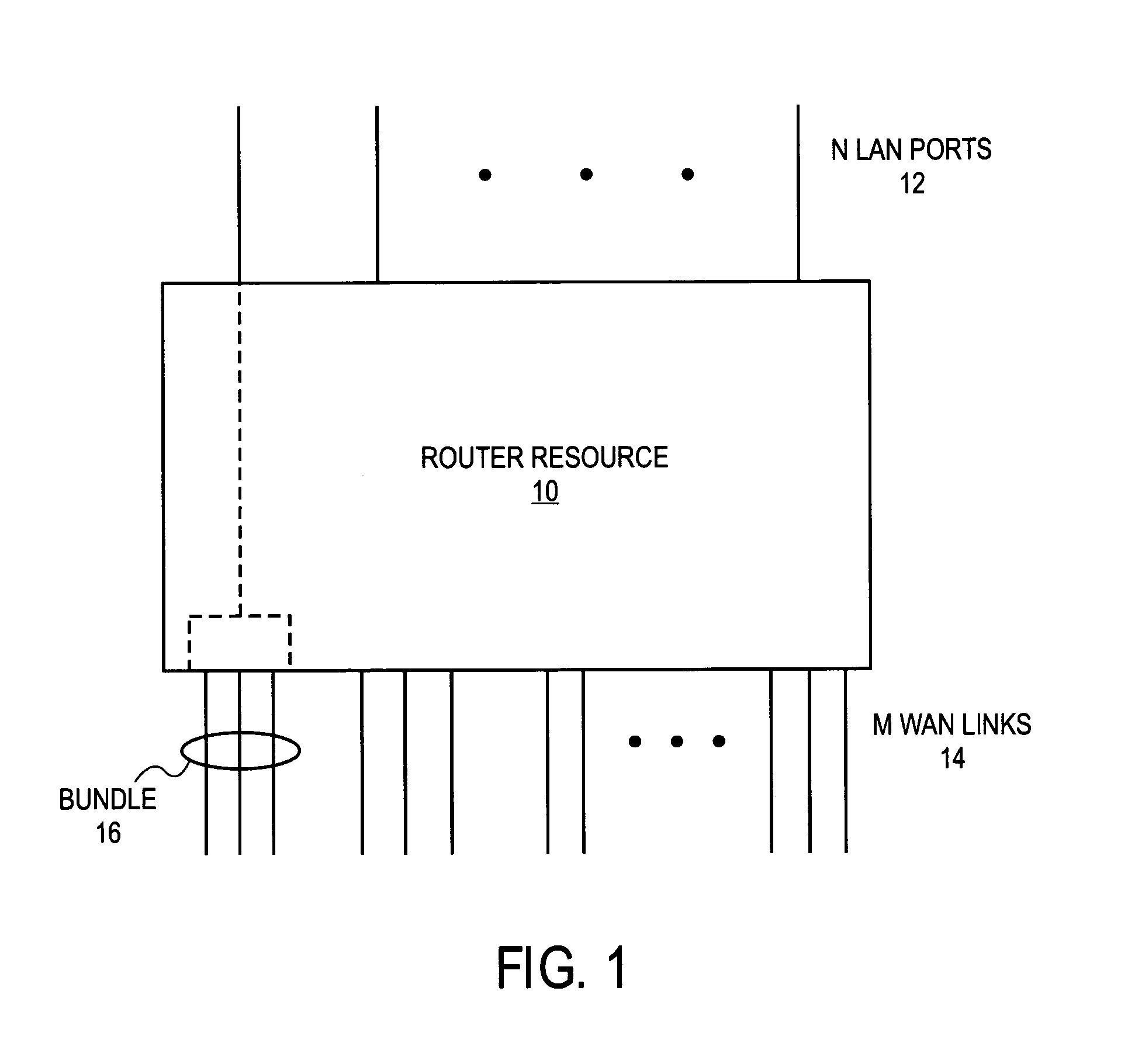
FIELD OF THE INVENTION[0001]The present invention relates generally to routing resources that may be used in packet switching networks and, in particular, to a scheme for allocating switching resources of such a router among multiple input interfaces thereof.BACKGROUND[0002]Routers are commonly used at interfaces between local area networks (LANs) and wide area networks (WANs). For example, routers may be used to multiplex between “N” number of LAN interfaces and “M” number of WAN interfaces. Sometimes, the WAN interfaces may be grouped into bundles through the use of a multi-link protocol, such as the multi-link point-to-point protocol (MLPPP). Such MLPPP bundles may be associated with a specific LAN interface by either a static or policy-based routing implementation.[0003]FIG. 1 illustrates a situation where a router resource 10 is used as an interface between N LAN ports 12 and M WAN links 14. The WAN links 14 are grouped into various bundles 16 of, for example, 3 4 or 5 WAN link...

Claims


Application Information

Patent Timeline
IPC IPC(8): H04L12/26
CPCH04L47/21H04L47/10
Inventor MOORE, PETE N.
Owner CISCO TECH INC
Learn More