Selective joint demodulation systems and methods for receiving a signal in the presence of noise and interference

Inactive Publication Date: 2006-03-21
ERICSSON INC
View PDF16 Cites 18 Cited by
  • Summary
  • Abstract
  • Description
  • Claims
  • Application Information

AI Technical Summary

Benefits of technology

[0008]According to another aspect of the present invention, the interfering signal includes an interfering signal synchronization word. The interfering signal synchronization word is found in the received signal, and the power of the interfering signal relative to the noise power is determined from the interfering signal synchronization word, to thereby determine the interference-to-noise ratio. Thus, the finding of t

Problems solved by technology

However, in many cases, the presence of an interfering signal depends on multipath and/or other distortions being introduced into the signal transmis

Method used


Image

  • Selective joint demodulation systems and methods for receiving a signal in the presence of noise and interference
  • Selective joint demodulation systems and methods for receiving a signal in the presence of noise and interference
  • Selective joint demodulation systems and methods for receiving a signal in the presence of noise and interference

Examples


Embodiment Construction

[0019]The present invention now will be described more fully hereinafter with reference to the accompanying drawings, in which preferred embodiments of the invention are shown. This invention may, however, be embodied in many different forms and should not be construed as limited to the embodiments set forth herein; rather, these embodiments are provided so that this disclosure will be thorough and complete, and will fully convey the scope of the invention to those skilled in the art. Like numbers refer to like elements throughout.

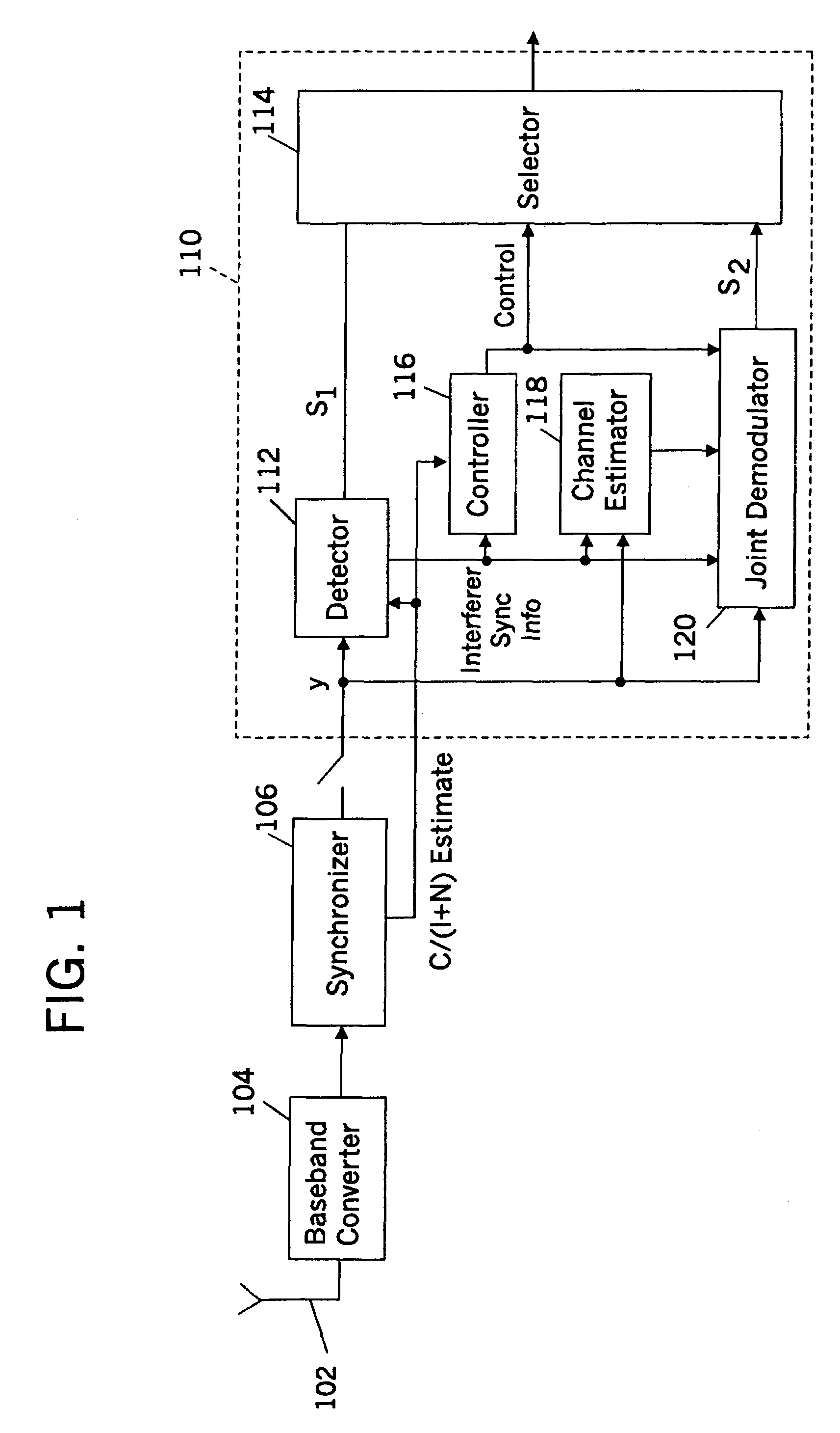
[0020]FIG. 1 is a block diagram of first embodiments of selective joint demodulation according to the present invention. Referring now to FIG. 1, a received signal is received from an antenna 102 and converted to a baseband representation by a baseband converter 104. Then, the signal may be passed through an analog-to-digital converter, sampled and sent to a synchronizer 106. The signal can be sampled once per symbol or multiple times per symbol, as in the...


PUM


Abstract

A signal is received in the presence of noise and interference by demodulating the signal when a relationship between the signal and the noise and the interference meets a criterion, and by jointly demodulating the signal when the relationship between the signal and the noise and the interference does not meet the criterion. Moreover, the signal may be demodulated if a relationship between the noise and the interference meets a second criterion and may be jointly demodulated if the relationship between the noise and the interference does not meet the second criterion. More specifically, demodulation may be performed when the signal-to-noise-and-interference ratio exceeds a first threshold and joint demodulation may be performed when the signal-to-noise-and-interference ratio is less than the first threshold. Moreover, the signal may be jointly demodulated if the interference-to-noise ratio exceeds a second threshold, and the signal may be demodulated if the interference-to-noise ratio is less than the second threshold. Thus, if the desired signal power is high relative to noise and interference, joint demodulation may be skipped and demodulation may be performed. Moreover, if the desired signal power is not large compared to interference-and-noise, joint demodulation may be used only when the interference power is high relative to the noise power. Finally, an interfering signal's synchronization word may be found in the received signal, and the power of the interfering signal relative to the noise power may be determined from the located interfering signal synchronization word, to thereby determine the interference-to-noise ratio. Moreover, the interfering signal's synchronization word that is detected can provide improved estimation of the interfering signal's channel estimate, which can be estimated in terms of the interfering signal's medium response compared to the composite channel response.

Description

BACKGROUND OF THE INVENTION[0001]This invention relates to digital communications, and more particularly to systems and methods for jointly demodulating a received signal in the presence of noise and interference.[0002]Joint demodulation is widely used to detect a desired signal from a received signal that includes an interfering signal as well. In joint demodulation, the desired signal and the interfering signal are both demodulated based on information concerning the desired signal and the interfering signal, so as to obtain a better estimate of the desired signal.[0003]Joint demodulation is described, for example, in U.S. Pat. No. 5,506,861 to Bottomley entitled System and Method for Joint Demodulation of CDMA Signals; U.S. Pat. No. 5,640,432 to Wales entitled Co-Channel Interference Suppression System; and U.S. patent application Ser. No. 09 / 143,821 to Hafeez et al., entitled Methods and Systems for Reducing Co-Channel Interference Using Multiple Timings for a Received Signal fi...

Claims


Application Information

Patent Timeline
IPC IPC(8): H04B1/69H03D1/04H04L27/00H04B1/7105H04B1/7107H04L1/00H04W24/08H04W28/00H04W28/18
CPCH04B1/7105H04B1/7107
Inventor MOLNAR, KARL J.
Owner ERICSSON INC
Why Eureka
Try Eureka