X-ray tube preheat control

Inactive Publication Date: 2006-03-21
MIDMARK
View PDF22 Cites 26 Cited by
  • Summary
  • Abstract
  • Description
  • Claims
  • Application Information

AI Technical Summary

Benefits of technology

[0008]When a line voltage is applied to the high voltage transformer, voltages are applied to the x-ray tube anode and cathode filament. The filament will not emit electrons instantaneously when a voltage is applied. The filament needs to be preheated before a steady flow of electrons will be emitted. The tube current fee

Problems solved by technology

That is, prior to the filament reaching an appropriate temperature for producing usable diagnostic x-rays, a plurality of preheat pulses are produced by applying a reduced kilovoltage potential to the x-ray tube, resulting in a number of pulses of non-usable unstable radiation.
Tho

Method used


Image

  • X-ray tube preheat control
  • X-ray tube preheat control
  • X-ray tube preheat control

Examples


Embodiment Construction

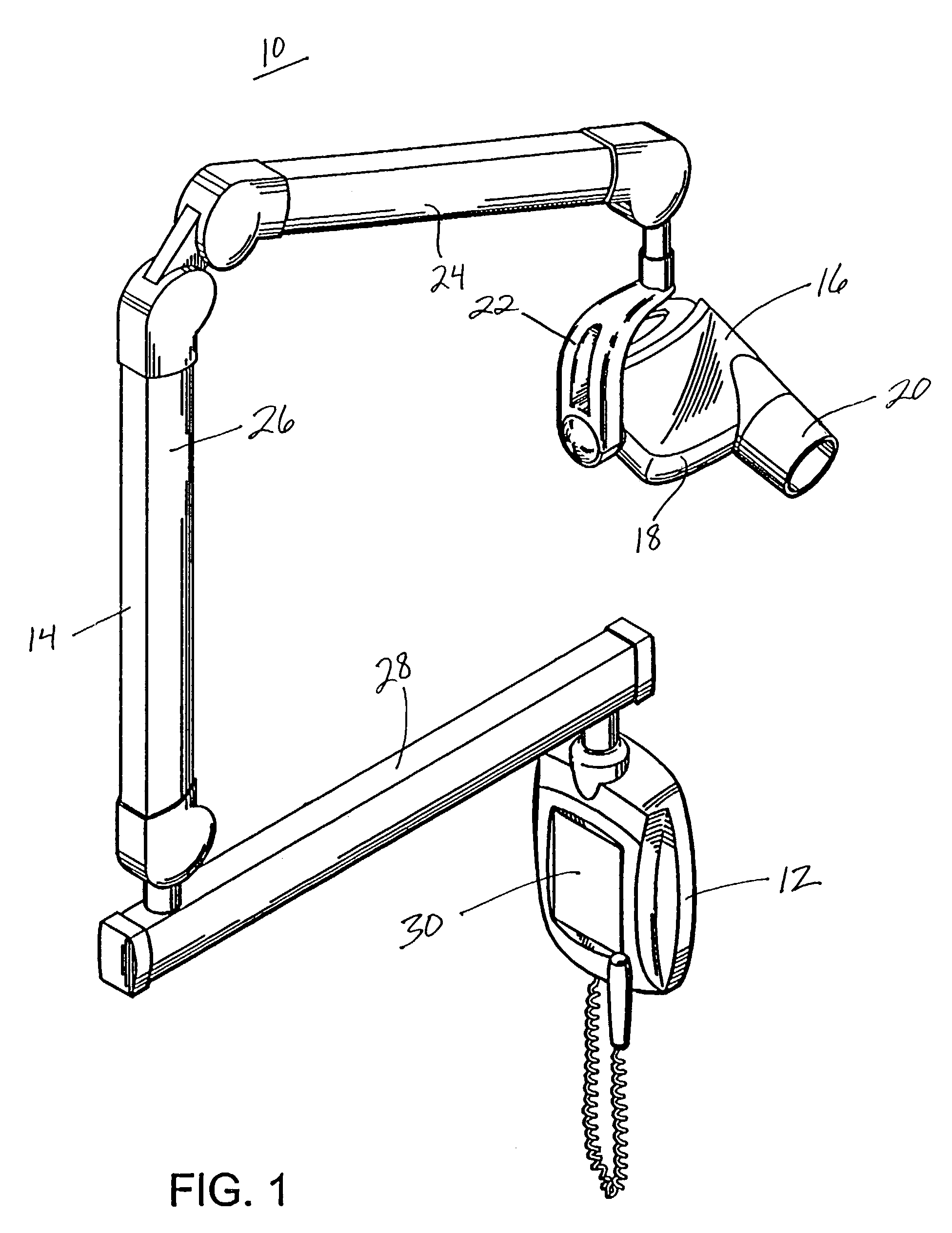
[0016]As shown in FIG. 1, a dental x-ray imaging system 10 includes a wall unit 12 as a source of power, an articulated arm assembly 14 connected at one end to the wall unit, and a tube head 16 connected to the opposite end of the arm assembly. The dental x-ray tube head 16 includes a tube end wall 18 to which a tubular assembly 20, also known as a cone, is attached or formed integrally therewith. The tube head 16 is connected to the end of the arm assembly 14 by a yoke 22 which allows the head to rotate about a first axis at the point where the yoke attaches to the head, while at the same time permitting rotation of the head about a second, transverse axis at the point where the yoke attaches to the arm. Yoke 22 is pivotably mounted to a first end of a first arm segment 24 of articulated arm assembly 14, which in turn is pivotably connected at its opposite end to a second arm segment 26. The latter is mounted for rotation about a vertical axis on the distal end of a horizontally sw...


PUM


Abstract

A current feedback circuit in a dental imaging apparatus, which measures the x-ray tube current produced by the x-ray filament. During preheat, when the tube current is sensed to be appropriate for production of a constant rate of electrons, preheat is stopped, and diagnostic radiation emission begins. This circuit eliminates a fixed amount of preheat pulses which contribute unusable radiation during preheat of the filament in prior art systems.

Description

BACKGROUND OF THE INVENTION[0001]The present invention relates to an x-ray imaging system, in particular, to a dental x-ray imaging system having x-ray tube preheat control circuitry for measuring the x-ray tube current and producing diagnostic radiation when the current is sensed to be appropriate for producing a constant rate of electrons.[0002]A dental x-ray imaging system customarily has an x-ray tube enclosed in a housing called a tube head. One face of the tube head has an opening through which the primary x-ray beam is projected from the x-ray tube target toward the examination subject. A tubular member, called a cone, is coupled to the tube head axially of the opening to limit the x-ray beam to the proper area on the subject's intraoral region.[0003]Some of the primary factors associated with diagnostic x-ray imaging apparatus include the peak voltage applied to the x-ray tube during exposure, the current forced through the x-ray tube in response to the selected peak voltage...

Claims


Application Information

Patent Timeline
IPC IPC(8): H05G1/32H05G1/34
CPCH05G1/34
Inventor KREMA, ALAN P.GRISER, LEGAL REPRESENTATIVE, VIRGINIA S.GRISER, DECEASED, JOHN T.
Owner MIDMARK
Why Eureka
Try Eureka