Image processing method, image processing apparatus, and programs thereof

a technology of image processing and image processing apparatus, applied in image data processing, instruments, printing, etc., can solve the problems of inability to provide corresponding ink color separation processing, inability to optimize inability to set optimized ucr and bg quantities for every hue, so as to reduce the influence of graininess, avoid distorted characteristic in lightness, hue and chroma, and effectively use a color reproduction region

Inactive Publication Date: 2006-03-21
CANON KK
View PDF15 Cites 47 Cited by
  • Summary
  • Abstract
  • Description
  • Claims
  • Application Information

AI Technical Summary

Benefits of technology

[0013]An object of the first invention is to effectively use a color reproduction region of an image formation apparatus and avoid to have distorted characteristic in lightness, hue and chroma.
[0014]An object of the second invention is to reduce the influence of graininess caused by K ink.

Problems solved by technology

However, conventionally, since the UCR quantity is calculated by multiplying a UCR coefficient μ by the Min(C, M, Y), and the BG quantity is calculated by multiplying the BG coefficient β by the UCR coefficient μ by the Min(C, M, Y), it was impossible to set optimized UCR and BG quantities for every hue, and as a result the following problems existed.
For a certain hue of a target printer, even though that color of higher chroma can be outputted, the ink color separation processing which would be needed to produce that color cannot be provided.
Again, even though the effect of graininess caused by the K ink can be reduced more based on appropriate combination of ink quantities, the corresponding ink color separation processing cannot be provided.
In the above conventional example, the non-linear characteristics that obtain in a case of the mixture of plural inks cannot be sufficiently compensated for or taken into account, and distorted characteristics remain in lightness, hue and chroma.

Method used


Image

  • Image processing method, image processing apparatus, and programs thereof
  • Image processing method, image processing apparatus, and programs thereof
  • Image processing method, image processing apparatus, and programs thereof

Examples


first embodiment

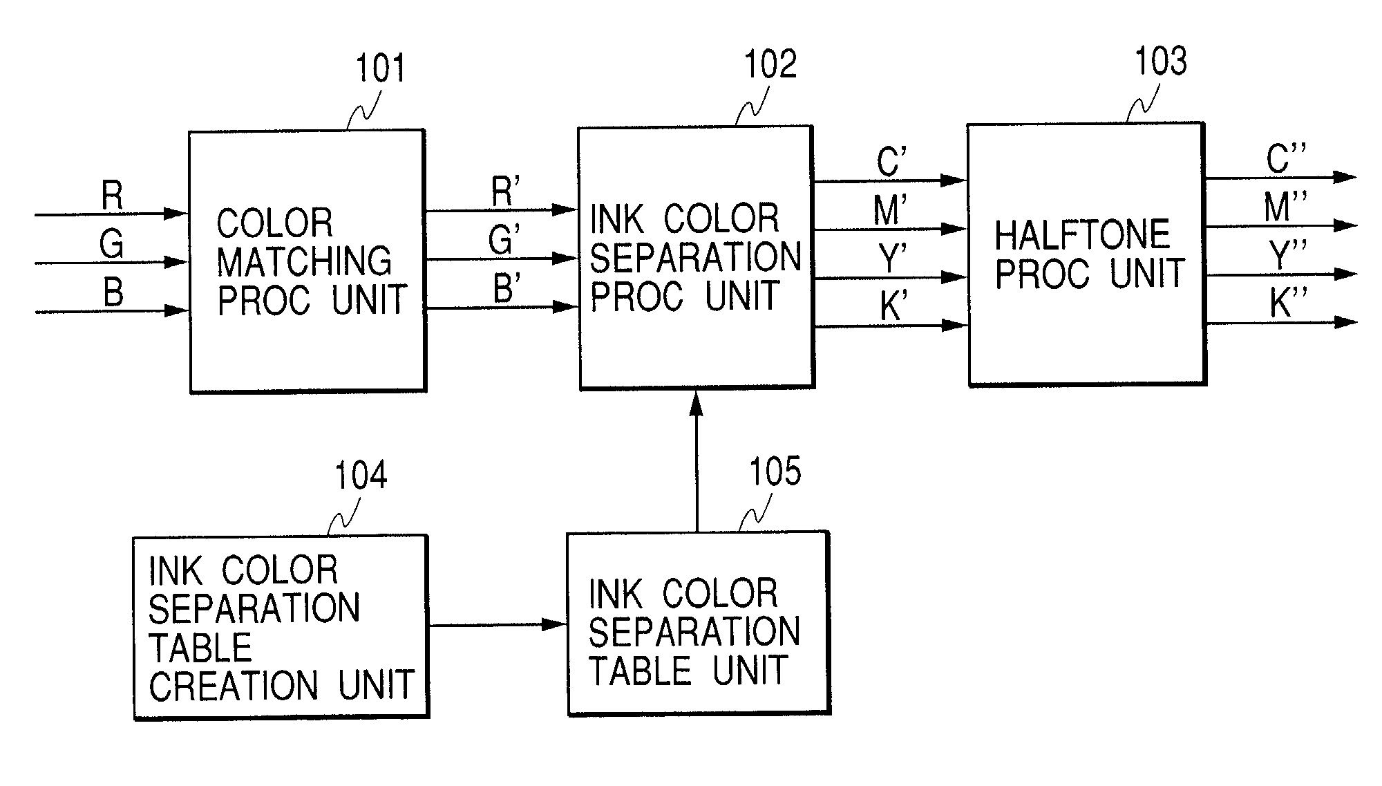
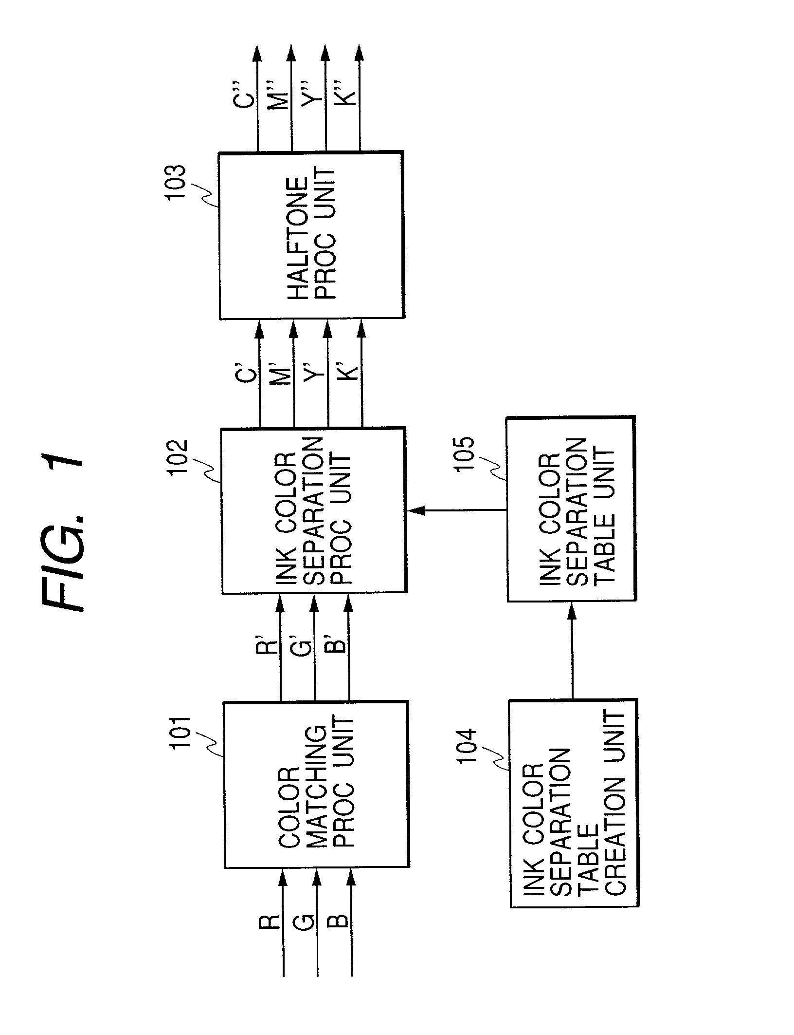
[0040]FIG. 1 is a view showing an outline of image processing according to the present embodiment.

[0041]Numeral 101 denotes a color matching processing unit for matching reproduction characteristics of R, G and B data with colors available in a printer.

[0042]Numeral 102 denotes an ink color separation processing unit for respectively converting R′, G′ and B′ multi-level data from the color matching processing unit 101 into the colors of the coloring agents C′ (cyan), M′ (magenta), Y′ (yellow) and K′ (black) available in the printer. Numeral 103 denotes a halftone processing unit for respectively converting C′, M′, Y′ and K′ multi-level data from the ink color separation processing unit 102 into data of a gradation number which can be expressed by the printer. Numeral 105 denotes an ink color separation table unit for providing a table (LUT: look-up table) used in executing interpolation processing in the ink color separation processing unit 102. Numeral 104 denotes an ink color sepa...

second embodiment

[0076]The second embodiment, which is obtained by modifying the first embodiment, executes non-linear approximation processing of ink quantity contour lines as in FIG. 16 in a step S7-5 shown in FIG. 15.

[0077]According to the second embodiment, a contour line varying rectangularly can be corrected into a contour line which is smoothly and sequentially varied.

[0078]Accordingly, generation of a pseudo-outline, even in cases of extreme changes in the ink quantity, can be suppressed.

[0079]In the following explanation, the processing that is the same as that in the first embodiment will be omitted from the explanation, and only processing different from that in the first embodiment will be explained.

[0080]In a case of executing two-dimensional interpolation processing on a target triangle in the step S5-3 shown in FIG. 5, the non-linear approximation processing of the above ink quantity contour lines is executed.

[0081]The two-dimensional interpolation processing for the target triangle e...

third embodiment

[0093]In the above embodiments, as ink colors available in a printer, a case of using four colors of C, M, Y and K is indicated. However, those embodiments can easily be applied to a printer in which are available a total of six colors, additionally using light and dark inks for cyan and magenta; this can be easily simply by adding two ink colors. In this case, similar to a case of setting the ink (K ink) dyeing point, a new UI of setting a dark ink dyeing start point is provided for the case in FIG. 21, and dark cyan and dark magenta ink dyeing points can be controlled in a manner such that dark ink dyeing points can be three-dimensionally and sequentially controlled by a total of seven points on lines W-Bk, W-C, W-M, W-Y, W-R, W-G and B-Bk.

[0094]In a case of dealing with another color ink than the C, M, Y and K colors, such as red, green or the like, intermediate points RM, RY, GY, and GC are newly set on intermediate portions between points R and M, R and Y, G and Y, and G and C....


PUM


Abstract

A color reproduction region of an image formation apparatus is to be effectively used and characteristic in lightness, hue and chroma is to be smoothed. In case of creating tables for separating color into color of coloring agent available in the image formation apparatus, a maximum line in the color reproduction region of the image formation apparatus is defined, internal lines in the color reproduction region of the image formation apparatus are defined and the tables are created by performing interpolation processing on the basis of the maximum line and the internal lines.

Description

BACKGROUND OF THE INVENTION[0001]1. Field of the Invention[0002]The present invention relates to creation of a table used for separating a given color into colors of the coloring agents available in a particular image formation apparatus.[0003]2. Related Background Art[0004]Conventionally, processing for separating a color into data corresponding to the coloring agents available in a color printer (hereinafter, called “ink color separation processing”) is as shown in FIG. 22. Hereinafter, an explanation of the ink color separation processing will be given with reference to FIG. 22.[0005]Numeral 2201 denotes a luminance / density conversion unit, numeral 2202 denotes a UCR / BG processing unit, numeral 2203 denotes a BG quantity setting unit and numeral 2204 denotes a UCR (under-color removal) quantity setting unit. In the luminance / density conversion unit 2201, luminance information of 8-bit data of R′, G′ and B′ that are being input is converted into C, M and Y data based on the follow...

Claims


Application Information

Patent Timeline
Patent Type & Authority Patents(United States)
IPC IPC(8): G06K9/00B41J2/52B41J2/525G06T1/00H04N1/46H04N1/60
CPCH04N1/6025
Inventor SAITO, KAZUHIROTORIGOE, MAKOTOIIDA, YOSHIKOSUWA, TETSUYA
Owner CANON KK
Why Eureka
Try Eureka