
System and method for interfacing multiple electronic devices

a technology of electronic devices and communication systems, applied in the direction of digital signal error detection/correction, instruments, recording signal processing, etc., can solve the problems of conflicting the needs of various devices, increasing the complexity of consumer electronics devices, and increasing the number of features

Inactive Publication Date: 2006-03-21
THOMSON LICENSING SA
View PDF25 Cites 73 Cited by
  • Summary
  • Abstract
  • Description
  • Claims
  • Application Information

AI Technical Summary

Benefits of technology

[0006]The invention resides, in part, in recognizing the described problems and, in part, in providing a system and method for solving these problems. Generally, the present invention defines a method for operating a video processing system by receiving initial copyright information from a first source, storing the initial copyright information, receiving updated copyright information from a second source, and updating the stored copyright information in response to the updated copyright information.

Problems solved by technology

Consumer electronics devices are becoming increasingly complex and provide an ever-increasing number of features.
While coupling these complex devices together via a data bus may be necessary to provide a complete audio-video (A / V) system, doing so creates numerous problems.
Conflicts between the needs of various devices may arise.

Method used


Image

  • System and method for interfacing multiple electronic devices
  • System and method for interfacing multiple electronic devices
  • System and method for interfacing multiple electronic devices

Examples


Embodiment Construction

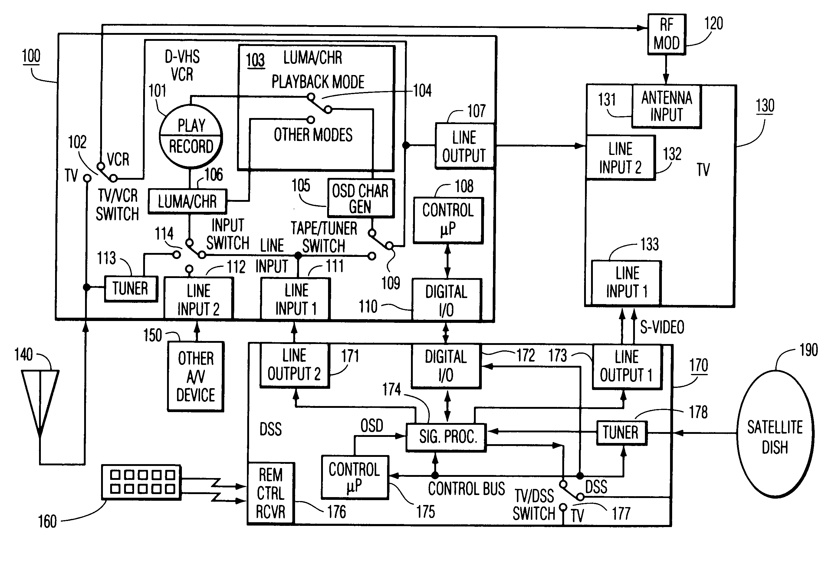
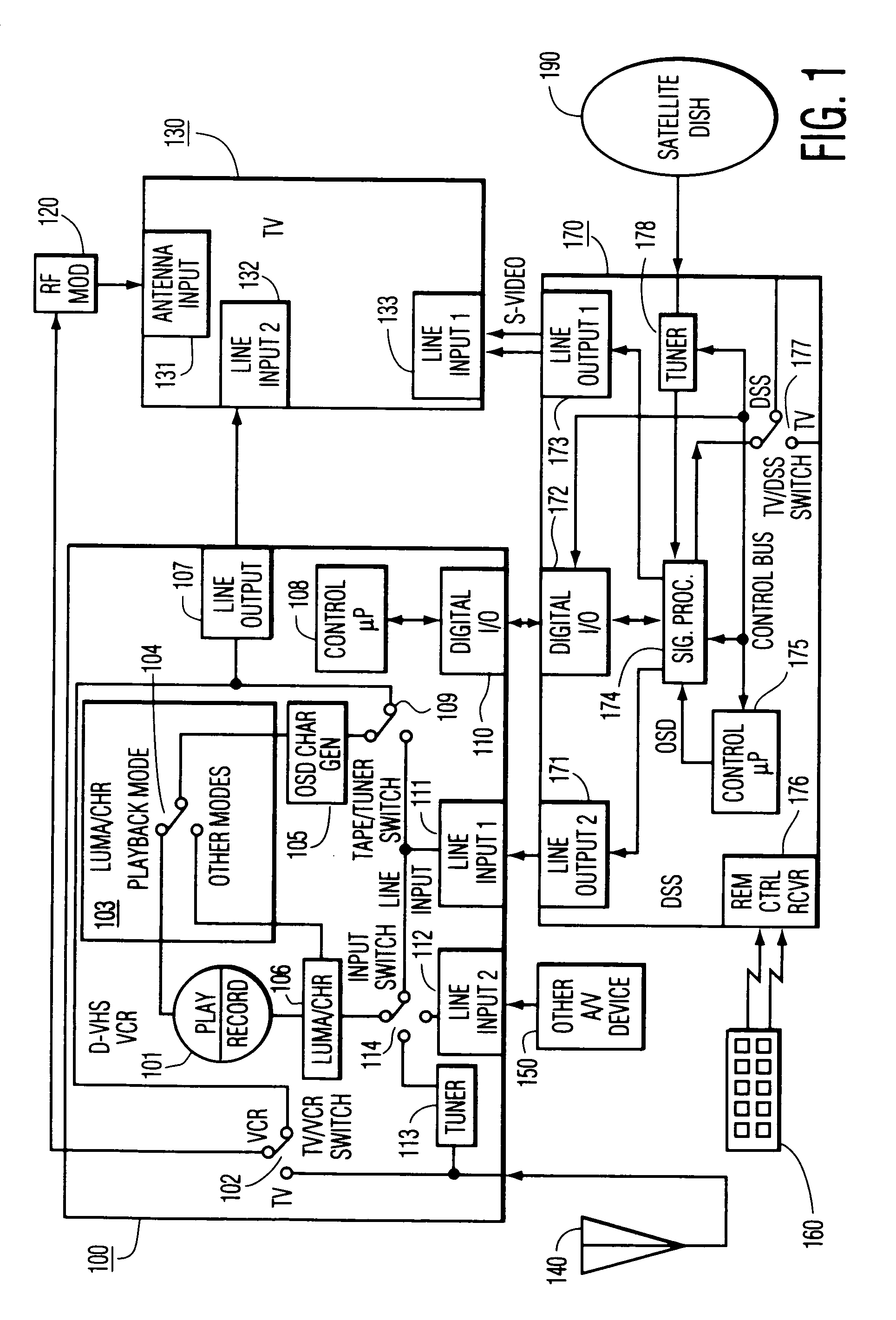
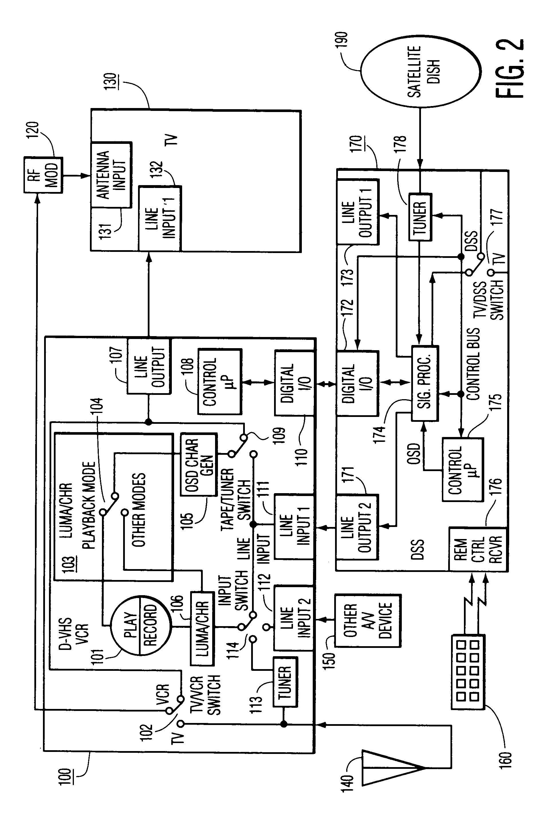
[0015]FIG. 1 shows a system interfacing multiple electronic devices including D- VHS VCR 100, DSS unit 170, TV 130, another A / V device 150, antenna 140 for receiving broadcast signals, remote control 160 for providing a user interface to DSS unit 170, satellite dish antenna 190 for receiving DSS signals, and RF modulator 120. VCR 100 includes play / record circuitry 101 which receives signals to be recorded from luma / chroma processor 106. Circuitry 101 outputs signals during playback to luma / chroma processor 103. Processor 103 also includes switch 104 for routing signals during playback mode and during other modes as shown. VCR 100 also includes tuner 113 for tuning a desired channel from the signal produced by antenna 140 and line inputs 111 and 112 for receiving composite television signals from other A / V device 150 and line output 171 of DSS unit 170, respectively. Line output 107 of VCR 100 provides a composite television signal output to line input 132 of TV 130. Digital I / O to V...


PUM

PropertyMeasurementUnit
timeaaaaaaaaaa
frequencyaaaaaaaaaa
Timeaaaaaaaaaa

Abstract

A method for operating a video processing system by receiving initial copyright information from a first source, storing the initial copyright information, receiving updated copyright information from a second source, and updating the stored copyright information in response to the updated copyright information. For example in one embodiment of the present invention, the initial copyright information for a program is received from an electronic program guide and updated copyright information is received along with the selected program. The video processing system may be programmed to operate in a first operating mode in response to the initial copyright information and the operating mode of the video processing system may be switched to a second operating mode in response to the updated copyright information.

Description

[0001]This is a division of application Ser. No. 09 / 177,278 filed on Nov. 30, 1998 now U.S. Pat. No. 6,507,953, and claims benefit of 60 / 011,023 filed on Feb. 02, 1996 and claims benefit of 60 / 015,035 filed on Apr. 08, 1996 and claims benefit of 60 / 028,651 filed on Oct. 16, 1996.FIELD OF THE INVENTION[0002]The invention involves systems for communicating between multiple electronic devices, such as consumer electronic devices, via interconnections such as digital data buses.BACKGROUND[0003]Data bus protocols such as the Consumer Electronics Bus, or CEBus, can be utilized for interconnecting consumer electronics devices such as television receivers, display devices, video-cassette recorders (VCR), and direct broadcast satellite (DBS) receivers. A bus protocol such as the CEBUS provides for communicating both control information and data. CEBus control information is communicated on a “control channel” having a protocol defined in Electronics Industries Association (EIA) specification...

Claims


Application Information

Patent Timeline
Patent Type & Authority Patents(United States)
IPC IPC(8): H04N7/16G11B20/00G11B15/02G11B20/10G11B20/18H04L9/32H04L12/22H04L12/28H04L12/40H04L12/403H04L12/64H04L29/06H04L29/08H04N5/44H04N5/445H04N5/76H04N5/765H04N5/775H04N5/782H04N5/91H04N5/913H04N5/92H04N5/926H04N5/93H04N7/08H04N7/081H04N9/79
CPCG11B20/00086H04L69/329G11B20/00144G11B20/00152G11B20/0021G11B20/00543G11B20/00666G11B20/0071G11B20/00753G11B20/0084G11B20/10H04L12/2803H04L12/2805H04L12/2814H04L12/282H04L12/403H04L12/413H04L29/06H04N5/4401H04N5/765H04N5/782H04N5/913H04N7/163H04N9/7921H04N9/7925H04N21/4147H04N21/4227H04N21/4334H04N21/43615H04N21/4583H04N21/4627H04N21/47214H04N21/4753H04N21/4882H04N21/8355H04L67/325H04L67/12H04L67/327G11B20/00137H04L12/2809H04L12/40117H04L2012/2841H04L2012/2849H04L2012/4026H04N5/775H04N5/7755H04N5/926H04N5/9305H04N21/4104H04N21/488H04N2005/91321H04N2005/91328H04L67/42H04N21/426H04N21/4112H04L67/63H04L67/62H04L12/28H04L65/00H04L9/40H04L67/01
Inventor HORLANDER, KARL FRANCISKVINTUS, JR., MICHAEL FRANCISWEHMEYER, KEITH REYNOLDSMILLER, ROBERT HOWARD
Owner THOMSON LICENSING SA
Learn More